Optical lens and imaging equipment

An optical lens and imaging surface technology, applied in optics, optical components, instruments, etc., can solve the problem that the imaging quality of the lens is greatly affected, and achieve the effect of improving the camera experience, realizing miniaturization, and achieving balance

Active Publication Date: 2021-01-29
合肥联创光学有限公司
View PDF2 Cites 0 Cited by
  • Summary
  • Abstract
  • Description
  • Claims
  • Application Information

AI Technical Summary

Problems solved by technology

However, the reduction in lens size has a great impact on the imaging quality of the lens, especially for wide-angle lenses with large fields of view

Method used


Image

  • Optical lens and imaging equipment
  • Optical lens and imaging equipment
  • Optical lens and imaging equipment

Examples


no. 1 example

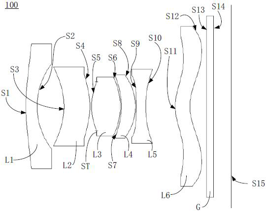
[0091] In the first embodiment of the present application, the vertical distance between the inflection point of the object side S11 of the sixth lens L6 and the optical axis is 1.488 mm.

[0092] Please refer to Table 1, the relevant parameters of each lens in the optical lens 100 provided by the first embodiment of the present application are shown in Table 1.

[0093] Table 1

[0094]

[0095] Please refer to Table 2, the surface coefficients of each aspheric surface of the optical lens 100 provided by the first embodiment of the present application are shown in Table 2:

[0096] Table 2

[0097]

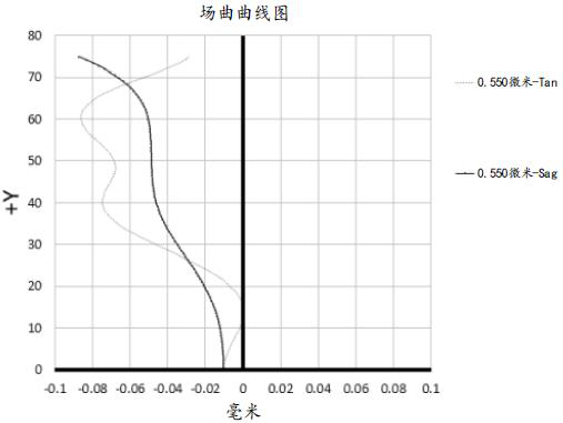
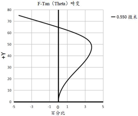
[0098] Please refer to figure 2 , image 3 , Figure 4 and Figure 5 , respectively showing the field curvature curve, the distortion curve, the vertical axis chromatic aberration curve and the axial chromatic aberration curve of the optical lens 100 .

[0099] figure 2 The field curvature curve of represents the degree of curvature of the meridian image plane and ...

no. 2 example

[0104] The structure of the optical lens 100 provided by the second embodiment of the present application is substantially the same as that of the optical lens 100 provided by the first embodiment, except that the curvature radius and material selection of each lens are different.

[0105] In the second embodiment of the present application, the vertical distance between the inflection point of the object side S11 of the sixth lens L6 and the optical axis is 1.348 mm.

[0106] Please refer to Table 3, the relevant parameters of each lens in the optical lens 100 provided by the second embodiment of the present application are shown in Table 3.

[0107] table 3

[0108]

[0109] Please refer to Table 4, the surface coefficients of each aspheric surface of the optical lens 100 provided by the second embodiment of the present application are shown in Table 4:

[0110] Table 4

[0111]

[0112] Please refer to Figure 6 , Figure 7 , Figure 8 and Figure 9 , respectively...

no. 3 example

[0118] The structure of the optical lens 100 provided by the third embodiment of the present application is substantially the same as that of the optical lens 100 provided by the first embodiment, except that the curvature radius and material selection of each lens are different.

[0119] In the third embodiment of the present application, the vertical distance between the inflection point of the object side S11 of the sixth lens and the optical axis is 1.218 mm.

[0120] Please refer to Table 5, the relevant parameters of each lens in the optical lens 100 provided by the third embodiment of the present application are shown in Table 5.

[0121] table 5

[0122]

[0123] Please refer to Table 6, the surface coefficients of each aspheric surface of the optical lens 100 in the third embodiment of the present application are shown in Table 6:

[0124] table 6

[0125]

[0126] Please refer to Figure 10 , Figure 11 , Figure 12 and Figure 13 , respectively showing t...


PUM


Abstract

The application provides an optical lens and an imaging device, which is composed of six lenses. The optical lens includes a first lens, a second lens, a diaphragm, a third lens, a fourth lens, The fifth lens and the sixth lens. The first lens has negative power, its object side is convex, and its image side is concave; the second lens has positive power, its object side is concave, and its image side is convex; the third lens has positive power, its object side is concave Both the and image sides are convex; the fourth lens has positive power, its object side is concave, and the image side is convex; the fifth lens has negative power, its object side and image side are both concave; the sixth lens has positive power Focus, the object side is convex at the near optical axis, the image side is concave at the near optical axis, and both the object side and the image side have at least one inflection point. The optical lens has a large wide angle and small distortion, and at the same time has a compact structure, which is conducive to realizing the miniaturization of the lens and high pixel balance.

Description

technical field [0001] The present application relates to the technical field of lens imaging, in particular to an optical lens and an imaging device. Background technique [0002] In recent years, camera lenses have been widely used in various fields, especially wide-angle lenses including ultra-wide-angle lenses and fisheye lenses play an important role in more and more occasions. In terms of photography, the wide-angle lens has the characteristics of short focus and large field of view, which can produce large barrel distortion to create special effects and bring strong visual impact to the observer. In terms of measurement, the wide-angle lens utilizes the characteristics of a large field of view to obtain more data in a single imaging to capture more scene information. At the same time, the market is increasingly demanding the miniaturization of lenses. However, the reduction in lens size has a great impact on the imaging quality of the lens, especially for wide-angle...

Claims


Application Information

Patent Timeline
Patent Type & Authority Patents(China)
IPC IPC(8): G02B13/00G02B13/18G02B13/06
CPCG02B13/0045G02B13/06G02B13/18
Inventor 曾昊杰于笑枝刘绪明曾吉勇
Owner 合肥联创光学有限公司
Why Eureka
Try Eureka