optical lens

An optical lens and lens technology, applied in the field of optical lens, can solve the problem that the screen-to-body ratio cannot be further improved, and achieve the effect of enhancing the sense of depth and space, compact structure, and good imaging quality

Active Publication Date: 2020-05-12
JIANGXI LIANYI OPTICS CO LTD
View PDF6 Cites 0 Cited by
  • Summary
  • Abstract
  • Description
  • Claims
  • Application Information

AI Technical Summary

Problems solved by technology

In recent years, as consumers are keen on the full screen of mobile phones, in addition to the demand for high pixels, the front lens is more pursuing visual simplicity; however, due to the large outer diameter and overall volume of the existing camera lens, "Notch screen" appeared, however, the area of ​​the notch is larger, that is, the opening area on the screen of the mobile phone is larger, and the screen-to-body ratio cannot be further improved

Method used


Image

  • optical lens
  • optical lens
  • optical lens

Examples


no. 1 example

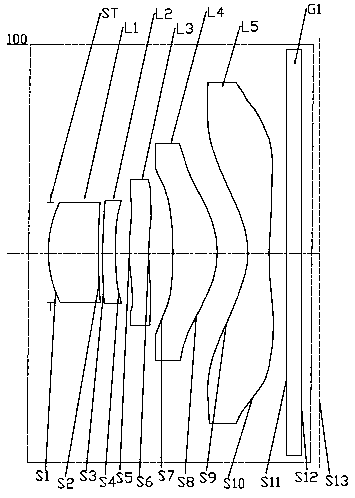
[0073] For the structural schematic diagram of the optical lens 100 provided by the first embodiment of the present invention, please refer to figure 1 , the optical lens 100 includes sequentially from the object side to the imaging surface along the optical axis: a stop ST, a first lens L1, a second lens L2, a third lens L3, a fourth lens L4, a fifth lens L5 and an infrared filter G1.

[0074] The first lens L1 is a plastic aspheric lens with positive refractive power, the object side S1 of the first lens is a convex surface, and the image side S2 of the first lens is a concave surface;

[0075] The second lens L2 is a plastic aspheric lens with negative refractive power, the object side S3 of the second lens is a convex surface, and the image side S4 of the second lens is a concave surface;

[0076] The third lens L3 is a plastic aspheric lens with positive refractive power, the object side S5 of the third lens is a convex surface, and the image side S6 of the third lens is...

no. 2 example

[0090] For the structural schematic diagram of the optical lens 200 provided in this embodiment, please refer to Figure 6 , the structure of the optical lens 200 in the present embodiment is roughly the same as that of the optical lens 100 in the first embodiment, the difference is that: the image side S2 of the first lens of the optical lens 200 in the present embodiment is a convex surface, and the second The object side surface S3 of the lens is concave, and the curvature radius and material selection of each lens are different.

[0091] The relevant parameters of each lens in the optical lens 200 provided in this embodiment are shown in Table 3.

[0092] table 3

[0093]

[0094] The surface coefficients of each aspheric surface of the optical lens 200 in this embodiment are shown in Table 4.

[0095] Table 4

[0096]

[0097]

[0098] In this embodiment, the curves of field curvature, distortion, axial point spherical aberration and lateral chromatic aberrati...

no. 3 example

[0100] For the structural schematic diagram of the optical lens 300 provided in this embodiment, please refer to Figure 11 The structure of the optical lens 300 in this embodiment is roughly the same as that of the optical lens 100 in the first embodiment, except that the radius of curvature and material selection of each lens of the optical mirror 300 in this embodiment are different.

[0101] The relevant parameters of each lens in the optical lens 300 provided in this embodiment are shown in Table 5.

[0102] table 5

[0103]

[0104]

[0105] Table 6 shows the surface coefficients of each aspheric surface of the optical lens 300 in this embodiment.

[0106] Table 6

[0107]

[0108] In this embodiment, the curves of field curvature, distortion, on-axis penalty spherical aberration and lateral chromatic aberration of the optical lens 300 are as follows Figure 12 , Figure 13 , Figure 14 and Figure 15 shown by Figure 12 to Figure 15 It can be seen that t...


PUM


Abstract

The invention provides an optical lens, which comprises in sequence from the object side to the imaging surface: a diaphragm; a first lens with positive refractive power, the object side is convex; a second lens with negative refractive power, the image side is concave The third lens with positive refractive power, its object side is convex, and the image side is concave; the fourth lens with positive refractive power, its image side is convex, and the object side is concave; the fifth lens with negative refractive power , the object side is concave at the near optical axis, and the image side is concave at the near optical axis; wherein, the entrance pupil diameter of the optical lens EPD<1.58mm; the effective diameter from the entrance pupil of the optical lens to the object side of the first lens The projection distance of the edge distance on the axis is greater than 0.17mm. The optical lens of the present invention adopts five lenses with specific refractive power, and adopts a specific surface shape and its matching, so that the effective imaging area of ​​the first lens becomes smaller, and the light entering area of ​​the lens on the screen becomes smaller, which can better It meets the needs of full-screen mobile phones.

Description

technical field [0001] The invention relates to the technical field of lens imaging, in particular to an optical lens. Background technique [0002] At present, with the popularization of portable electronic devices (such as smartphones, tablets, and cameras), coupled with the popularity of social, video, and live broadcast software, people are more and more fond of photography, and camera lenses have become a must for electronic devices. Standard configuration, camera lenses have even become the primary consideration for consumers when purchasing electronic equipment. [0003] With the continuous development of mobile information technology, portable electronic devices such as mobile phones are also developing in the direction of ultra-thin, full-screen, ultra-high-definition imaging, etc., which puts forward higher requirements for camera lenses mounted on portable electronic devices . In recent years, as consumers are keen on the full screen of mobile phones, in additio...

Claims


Application Information

Patent Timeline
Patent Type & Authority Patents(China)
IPC IPC(8): G02B13/00G02B13/18G02B1/04
CPCG02B1/041G02B13/0045G02B13/18G02B27/0012G02B27/0025G02B15/145113G02B9/60
Inventor 王义龙刘绪明曾昊杰曾吉勇
Owner JIANGXI LIANYI OPTICS CO LTD
Why Eureka
Try Eureka