Optical lens and imaging equipment

An optical lens and imaging surface technology, applied in the field of imaging lenses, can solve the problems of not being able to bring visual experience to consumers, the size of the front camera head is large, and the screen ratio is difficult to increase, so as to meet the needs of high screen ratio, Small overall length, reasonable setting effect

Active Publication Date: 2021-12-21
合肥联创光学有限公司
View PDF6 Cites 4 Cited by
  • Summary
  • Abstract
  • Description
  • Claims
  • Application Information

AI Technical Summary

Problems solved by technology

In recent years, the continuous development of special-shaped screens such as water drop screens, notch screens, and hole-digging screens are all due to consumers' keen pursuit of full-screen mobile phones; due to the existence of the front camera and the excessive size of the head, the full-screen There are still many obstacles to the realization of
The outer diameter of the head of the optical lens commonly used in the market is as small as ∅3mm. Due to the larger outer diameter and overall volume of the head, it is difficult to increase the screen ratio and cannot bring consumers better visual experience

Method used


Image

  • Optical lens and imaging equipment
  • Optical lens and imaging equipment
  • Optical lens and imaging equipment

Examples


no. 1 example

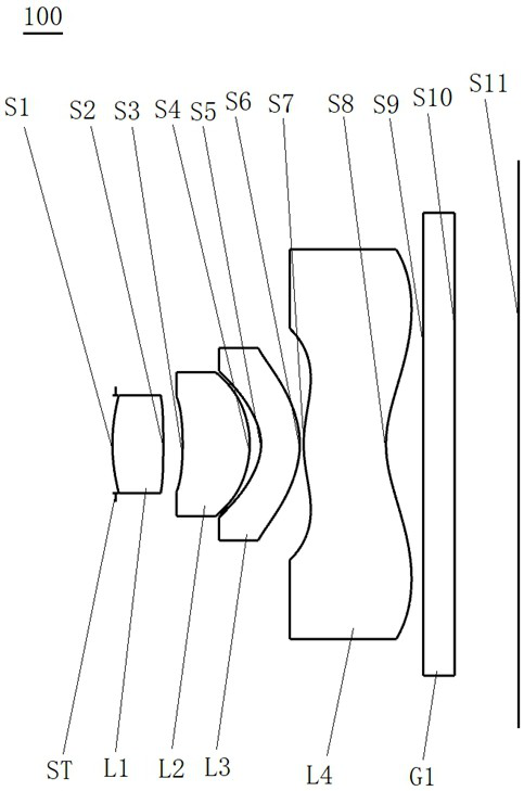
[0079] see figure 1 , which is a schematic structural view of the optical lens 100 provided in the first embodiment of the present invention, the optical lens 100 includes in sequence from the object side to the imaging surface along the optical axis: a stop ST, a first lens L1, a second lens L2, a second lens L2, Three lenses L3, a fourth lens L4 and a filter G1.

[0080] The first lens L1 has a positive refractive power, the object side S1 of the first lens is a convex surface, and the image side S2 of the first lens is a convex surface;

[0081] The second lens L2 has positive refractive power, the object side S3 of the second lens is concave, and the image side S4 of the second lens is convex;

[0082] The third lens L3 has negative refractive power, the object side S5 of the third lens is concave, and the image side S6 of the third lens is convex;

[0083] The fourth lens L4 has positive refractive power, the object side S7 of the fourth lens is convex at the near optic...

no. 2 example

[0093] For the structural schematic diagram of the optical lens 200 provided in this embodiment, please refer to Figure 6 , the structure of the optical lens 200 in this embodiment is substantially the same as that of the optical lens 100 in the first embodiment, the difference mainly lies in the design parameters.

[0094] The relevant parameters of each lens in the optical lens 200 provided in this embodiment are shown in Table 3.

[0095] table 3

[0096]

[0097] The surface coefficients of each aspheric surface of the optical lens 200 in this embodiment are shown in Table 4.

[0098] Table 4

[0099]

[0100] In this embodiment, the curves of field curvature, distortion, axial point spherical aberration and lateral chromatic aberration of the optical lens 200 are as follows Figure 7 , Figure 8 , Figure 9 and Figure 10 shown by Figure 7 to Figure 10 It can be seen that the curvature of field is controlled within ±0.05mm, the optical distortion is control...

no. 3 example

[0102] For the structural schematic diagram of the optical lens 300 provided in this embodiment, please refer to Figure 11 , the structure of the optical lens 300 in this embodiment is roughly the same as that of the optical lens 100 in the first embodiment, the difference mainly lies in the design parameters.

[0103] The relevant parameters of each lens in the optical lens 300 provided in this embodiment are shown in Table 5.

[0104] table 5

[0105]

[0106] Table 6 shows the surface coefficients of each aspheric surface of the optical lens 300 in this embodiment.

[0107] Table 6

[0108]

[0109] In this embodiment, the curves of field curvature, distortion, axial point spherical aberration and lateral chromatic aberration of the optical lens 300 are as follows Figure 12 , Figure 13 , Figure 14 and Figure 15 shown by Figure 12 to Figure 15 It can be seen that the curvature of field is controlled within ±0.05mm, the optical distortion is controlled with...


PUM


Abstract

The invention discloses an optical lens and imaging equipment. The optical lens sequentially comprises, from an object side to an imaging surface along an optical axis, a diaphragm;p a first lens with positive focal power, wherein the object side surface and the image side surface of the first lens are convex surfaces; a second lens with positive focal power, wherein the object side surface of the second lens is a concave surface, and the image side surface of the second lens is a convex surface; a third lens with negative focal power, wherein the object side surface of the third lens is a concave surface, and the image side surface of the third lens is a convex surface; a fourth lens with positive focal power, wherein the object side surface of the fourth lens is a convex surface near the optical axis, the image side surface of the fourth lens is a concave surface near the optical axis, and the object side surface and the image side surface of the fourth lens have inflection points, wherein the first lens, the second lens, the third lens and the fourth lens are all aspherical lenses, the entrance pupil diameter EPD of the optical lens is less than 0.9 mm, and the total optical length TTL of the optical lens is less than 3.8 mm. The optical lens has the advantages of small outer diameter of the head, small size and high pixel.

Description

technical field [0001] The invention relates to the technical field of imaging lenses, in particular to an optical lens and imaging equipment. Background technique [0002] At present, with the popularity of portable electronic devices and the popularity of social networking, video, and live broadcast software, people are more and more fond of photography. Camera lenses have become standard equipment for electronic equipment, and camera lenses have even become consumer It is the index that consumers consider first when purchasing electronic equipment. [0003] With the continuous development of mobile information technology, portable electronic devices such as mobile phones are also developing in the direction of ultra-thin, full-screen, ultra-high-definition imaging, etc., which puts forward higher requirements for camera lenses mounted on portable electronic devices , not only must have sufficient optical performance and imaging capabilities, but also have a certain aesth...

Claims


Application Information

Patent Timeline
Patent Type & Authority Applications(China)
IPC IPC(8): G02B13/00G02B13/18G03B30/00
CPCG02B13/004G02B13/18G03B30/00
Inventor 章彬炜肖国亮曾昊杰
Owner 合肥联创光学有限公司
Why Eureka
Try Eureka