
Debugging method and device for display panel

A technology of display panel and debugging method, applied in static indicators, instruments, etc., can solve the problem of uneven charging, and achieve the effect of increasing adjustability, improving moiré phenomenon, and improving display quality

Active Publication Date: 2021-06-01
TCL CHINA STAR OPTOELECTRONICS TECH CO LTD
View PDF8 Cites 0 Cited by
  • Summary
  • Abstract
  • Description
  • Claims
  • Application Information

AI Technical Summary

Problems solved by technology

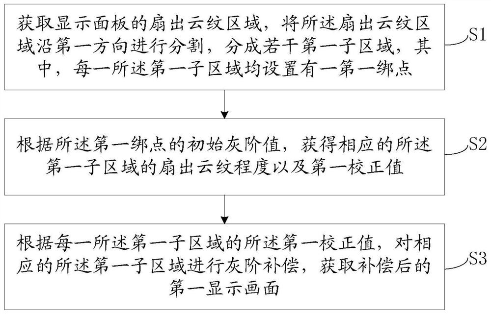
[0006] The purpose of this application is to provide a display panel debugging method and device, which can improve the problem of uneven charging caused by the different lengths of the central data line and the data lines on both sides in the area of ​​each data integrated circuit

Method used


Image

  • Debugging method and device for display panel
  • Debugging method and device for display panel
  • Debugging method and device for display panel

Examples


Embodiment Construction

[0019] The technical solutions in the embodiments of the present application will be clearly and completely described below in conjunction with the drawings in the embodiments of the present application. Apparently, the described embodiments are only some of the embodiments of this application, not all of them. Based on the embodiments in this application, all other embodiments obtained by those skilled in the art without making creative efforts belong to the scope of protection of this application.

[0020] In the description of the present application, it should be understood that the terms "first" and "second" are used for description purposes only, and cannot be interpreted as indicating or implying relative importance or implicitly indicating the quantity of indicated technical features. Thus, a feature defined as "first" or "second" may explicitly or implicitly include one or more of said features. In the description of the present application, "plurality" means two or ...


PUM


Abstract

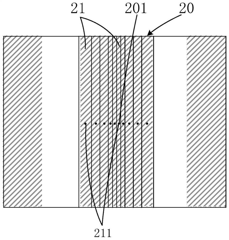
The present application discloses a debugging method and device for a display panel. The method includes: acquiring a fan-out moiré area of ​​a display panel, dividing the fan-out moiré area along a first direction into several first sub-areas, wherein each first sub-area is provided with a first binding point ; According to the initial grayscale value of the first binding point, obtain the fan-out moiré degree of the corresponding first subregion and the first correction value; According to the first correction value, perform grayscale compensation on the corresponding first subregion, and obtain The first display screen after compensation. The present application solves the problem of uneven charging in the area of ​​the data integrated circuit, improves the moiré phenomenon in the fan-out area, ensures the uniformity of image quality, and improves the display quality of the product.

Description

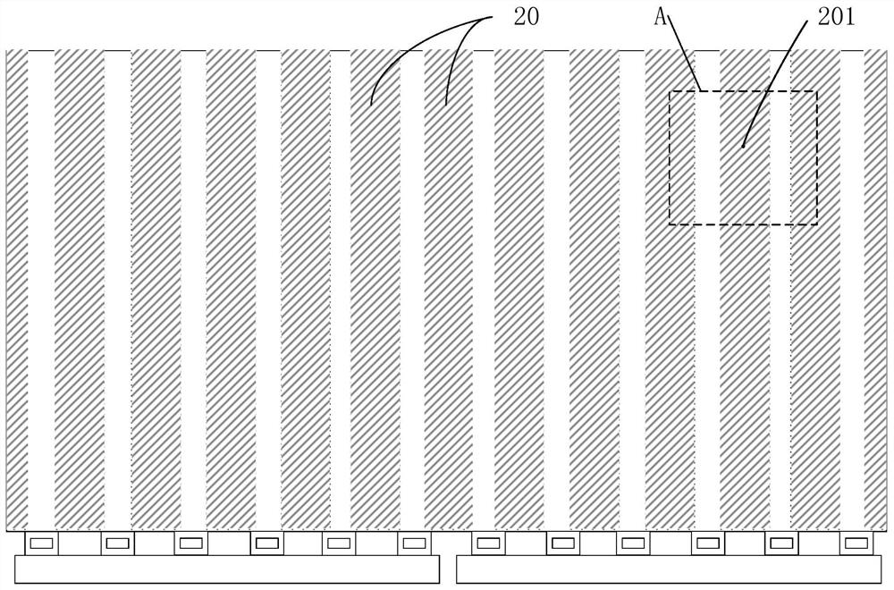
technical field [0001] The present application relates to the field of display technology, in particular to a debugging method and device for a display panel. Background technique [0002] Large-size panels have the problem of RC delay, which leads to uneven charging of pixels in each area and affects product quality. The length of the data line in the middle of each data integrated circuit (Data IC) of the LCD panel is shorter than that on both sides, that is, the resistance and capacitance on the center line of the data IC is smaller than the resistance and capacitance on the line at the border. Therefore, in a short charging time, the brightness of the edge portion of the data integrated circuit is obviously lower than that of the middle portion, and this phenomenon is called fan-out moiré (fan-outmura). [0003] In the prior art, the charging time of the wires at the edge and the middle of the data integrated circuit is controlled to improve the fan-out moiré effect. H...

Claims


Application Information

Patent Timeline
Patent Type & Authority Patents(China)
IPC IPC(8): G09G3/36
CPCG09G3/36
Inventor 杨惠高翔
Owner TCL CHINA STAR OPTOELECTRONICS TECH CO LTD
Learn More