Pressure relief system and method for integral leak rate test of AP1000 containment

A containment and leakage rate technology, which is applied in the field of overall containment leakage rate test, can solve problems such as unsuitable for renovation and expansion, long time occupied by the main line, and limited space, so as to shorten the time for refueling and overhaul, shorten the time occupied by the main line, and improve The effect of economic benefits

Active Publication Date: 2020-12-04
SANMEN NUCLEAR POWER CO LTD
View PDF5 Cites 1 Cited by
  • Summary
  • Abstract
  • Description
  • Claims
  • Application Information

AI Technical Summary

Problems solved by technology

During the overall leak rate test of the containment, in order to realize the pressure filling and unloading of the containment, the VFS-PL-V202 and VFS-PL-V009 on the filling and unloading flow channel are kept open and cannot be closed or adjusted.
However, VFS-PL-V010 and VFS-PL-V005 are used as on-off valves, which do not have the ability to adjust the exhaust gas of 0.402MPa to the pressure range that the downstream pipe

Method used


Image

  • Pressure relief system and method for integral leak rate test of AP1000 containment

Examples


Embodiment Construction

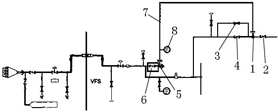
[0032] The technical solutions of the present invention will be further described below in conjunction with the accompanying drawings and through specific implementation methods.

[0033] like figure 1 As shown, a pressure relief system for AP1000 containment overall leakage rate test, including pressure relief valve 1 3, pressure relief valve 2 4, isolation valve 6, three-way one 1, butterfly valve 2, three-way two 5, VFS exhaust air Filter unit, temporary pressure relief hose 7 and local pressure gauge 8.

[0034] Pressure relief valve 1 3 is used to realize the adjustment function of pressure relief for the overall containment leakage rate test, pressure relief valve 2 4 is used to assist pressure relief valve 1 3 to realize the adjustment function of pressure relief for the overall containment leakage rate test, isolation valve 6 is always in a closed state, which is used to isolate the air flow on the upstream and downstream sides of the isolation valve 6 . Tee one 1 is...


PUM

PropertyMeasurementUnit
Diameteraaaaaaaaaa
Diameteraaaaaaaaaa

Abstract

The invention relates to the technical field of containment overall leakage rate tests, and particularly relates to a pressure relief system and method for an integral leak rate test of an AP1000 containment. The pressure relief system for the integral leak rate test of the AP1000 containment comprises a pressure relief valve I, a pressure relief valve II, an isolation valve, a tee joint I, a butterfly valve, a tee joint II, a VFS exhaust air filter unit and a temporary pressure relief hose, wherein the pressure relief valve I and the pressure relief valve II are arranged in parallel; the teejoint I is arranged on a discharge pipeline at the downstream of the pressure relief valve I and the pressure relief valve II; the butterfly valve is arranged on the discharge pipeline between the teejoint I and a chimney; the tee joint II is arranged on the exhaust pipeline between the downstream of the isolation valve and the chimney; the VFS exhaust air filter unit is arranged on the exhaust pipeline between the tee joint II and the chimney; one end of the temporary pressure relief hose is connected with the tee joint I, and the other end of the temporary pressure relief hose is connectedwith the tee joint II. According to the pressure relief system for the integral leak rate test of the AP1000 containment, the VUS and the VFS are combined to change a pressure relief flow channel forthe integral leak rate test of the unit overhaul containment, the purpose of purifying pressure relief air is achieved, and thus the nuclear safety guide rule is met.

Description

technical field [0001] The invention relates to the technical field of the overall containment leak rate test, in particular to a pressure relief system and method for the AP1000 containment overall leak rate test. Background technique [0002] According to the requirements of nuclear safety guidelines (HAD401 / 02), during the refueling and overhaul phase of nuclear power plants, the depressurized air used for performing the overall containment leakage rate test must be filtered and purified before being discharged. However, the flow path of the existing AP1000 containment leak rate test system (VUS) cannot meet the nuclear safety guidelines: the pressure relief and exhaust path of the pre-operation containment leak rate test performed during commissioning is from the containment exhaust filter through the exhaust air. After passing through the containment penetration, the pipeline is decompressed by VUS-PL-V002 / 003 and then discharged to the high altitude of the chimney of t...

Claims


Application Information

Patent Timeline
IPC IPC(8): G21C17/00G21C19/00G21D1/02
CPCG21C17/002G21C19/00G21D1/02Y02E30/30Y02E30/00
Inventor 缪骐远白东进熊壮王子虎
Owner SANMEN NUCLEAR POWER CO LTD
Why Eureka
Try Eureka