Eye massager and massaging machine core thereof
A movement and connecting rod technology, applied in roller massage, massage aids, instruments for compressing reflex points, etc., can solve problems such as insufficient comfort, dry eyes, soreness, etc., and achieve suitable massage intensity and good comfort. Effect
- Summary
- Abstract
- Description
- Claims
- Application Information
AI Technical Summary
Problems solved by technology
Method used
Image
Examples
Embodiment 1
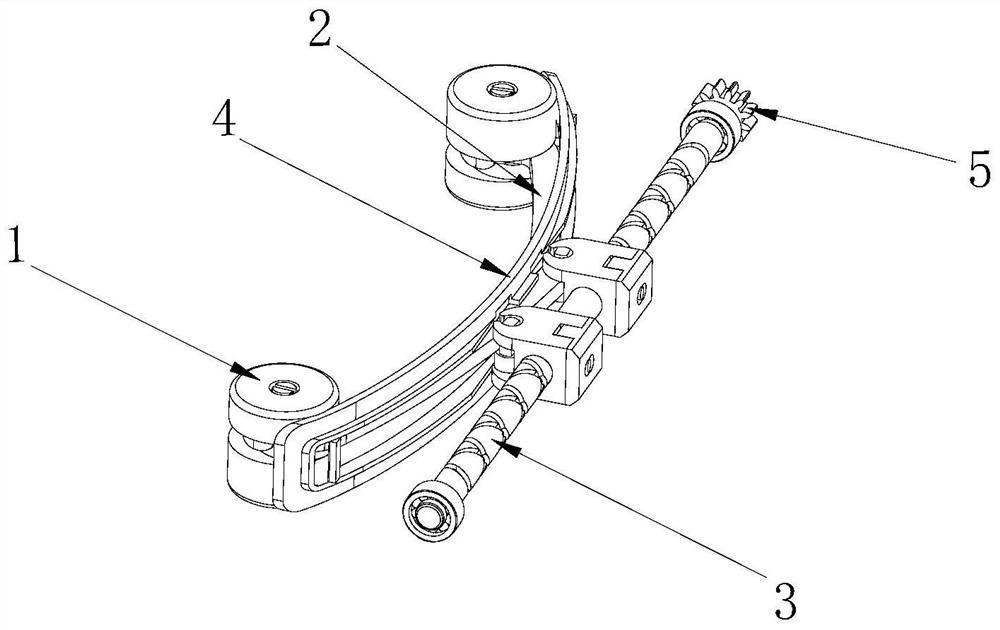
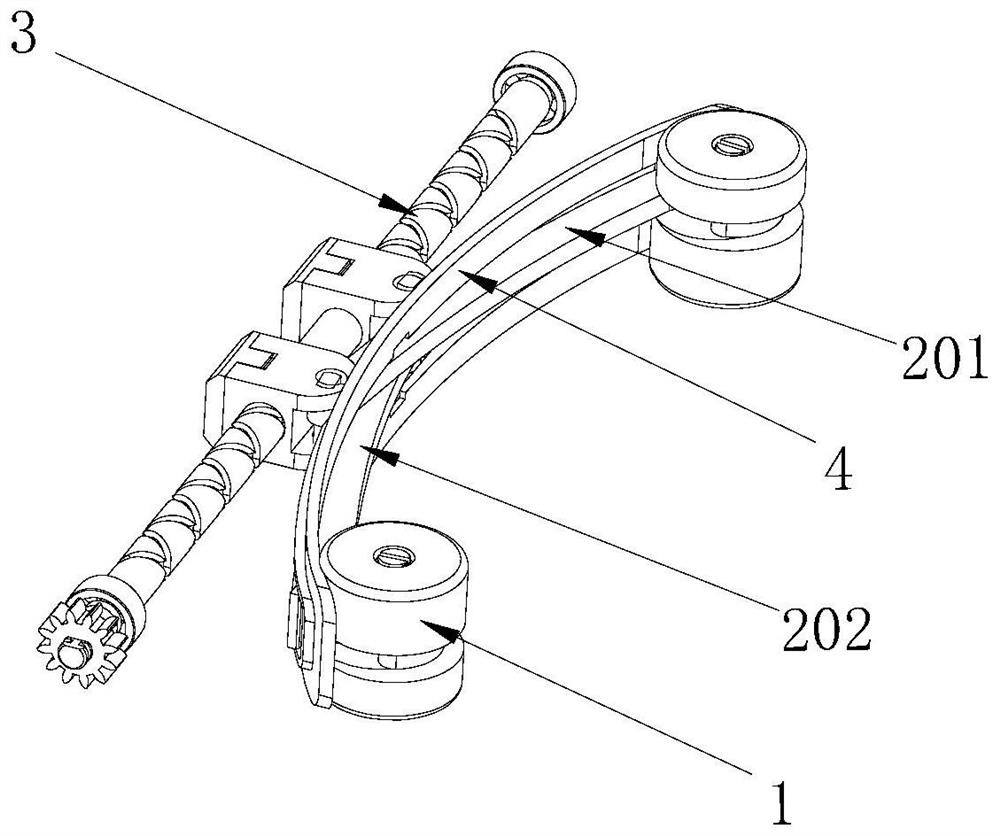
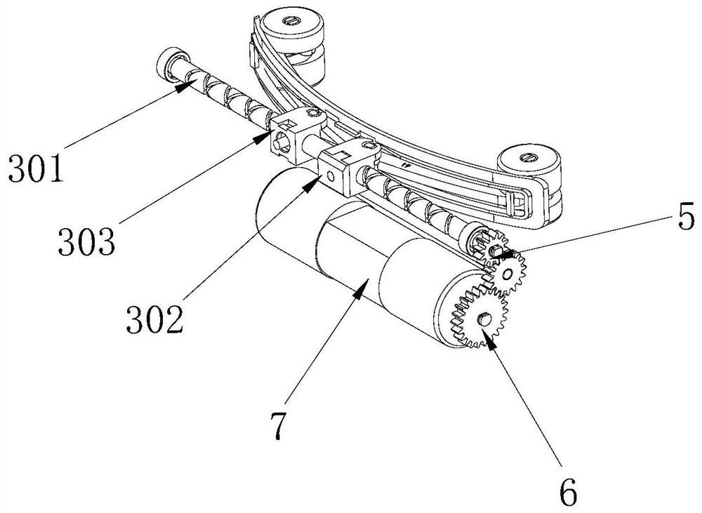
[0038] Such as Figure 1-6 As shown, this application provides a massage movement, including a massage assembly 1, a connecting rod assembly 2 and a transmission assembly 3, wherein the connecting rod assembly 2 includes a movable cross first connecting rod 201 and a second connecting rod 202, the first One end of a connecting rod 201 is connected to the transmission assembly 3, and the other end is suspended in the air; one end of the second connecting rod 202 is connected to the transmission assembly 3, and the other end is suspended in the air. The massage assembly 1 is arranged in the first connecting rod 201 and the second connecting rod 202 In this embodiment, the free end of the first connecting rod 201 and the free end of the second connecting rod 202 are provided with a massage assembly 1 .
[0039] Further, the transmission assembly 3 is configured to drive the suspended end of the first connecting rod 201 and the suspended end of the second connecting rod 202 to rec...
Embodiment 2
[0048] Please refer to Figure 7-8 , the difference between this embodiment and embodiment 1 is that the structure of the transmission assembly 3 is different. In this embodiment, the transmission assembly 3 also includes an electronic limit switch plate 305, and the screw is a sliding screw 304, and the electronic limit The switch plate 305 is fixed on the sliding screw rod 304 between the first connecting unit 302 and the second connecting unit 303, and the first connecting unit 302 and the second connecting unit 303 are respectively slidably arranged on the sliding screw rod 304. The rod 201 and the second connecting rod 202 are connected to the first connecting unit 302 and the second connecting unit 303 respectively; 304 on the third slider 306 and the fourth slider 307, and the third slider 306 and the fourth slider 307 at the front end is provided with the second bayonet 13, the first connecting rod 201 and the second connecting rod 202 are not A third mounting post 14...
Embodiment 3
[0051] Please refer to Figure 9-12 The difference between this embodiment and Embodiment 1 is that the connecting rod assembly 2 used is different. In this embodiment, the connecting rod assembly 2 also includes a first slide rail 15 arranged on the first The second sliding rail 16 on the two connecting rods 202, the first sliding rail 15 and the second sliding rail 16 are all provided with a through groove 17 for guiding the first connecting rod 201 and the second connecting rod 202, wherein the first The connecting rod 201 includes a first sub-rod 18, a second sub-rod 19, a first guide post 21 and a second guide post 20. One end of the first sub-rod 18 is connected to the transmission assembly 3, and the other end is connected to the second sub-rod 19. One end is pivotally connected, the other end of the second sub-rod 19 is suspended, the first slide rail 15 is arranged on the first sub-rod 18, and the first guide column 21 is accommodated in the through groove 17 of the f...
PUM
 Abstract
Description
Claims
Application Information
 - R&D
- Intellectual Property
- Life Sciences
- Materials
- Tech Scout
- Unparalleled Data Quality
- Higher Quality Content
- 60% Fewer Hallucinations
Browse by: Latest US Patents, China's latest patents, Technical Efficacy Thesaurus, Application Domain, Technology Topic, Popular Technical Reports.
© 2025 PatSnap. All rights reserved.Legal|Privacy policy|Modern Slavery Act Transparency Statement|Sitemap|About US| Contact US: help@patsnap.com


