
Clamping device for automatic equipment part machining

A technology for clamping devices and parts, applied in workpiece clamping devices, manufacturing tools, etc., can solve the problems of unstable fixation, shaking of automation equipment parts, etc., and achieve convenient clamping, convenient positioning and adjustment of the position of the tightening ring Effect

Inactive Publication Date: 2020-12-08
周洁
View PDF0 Cites 2 Cited by
  • Summary
  • Abstract
  • Description
  • Claims
  • Application Information

AI Technical Summary

Problems solved by technology

[0003] When the existing clamping device for processing parts of automation equipment is in use, it will be unstable due to the limitation of the device, causing the parts of automation equipment to shake when it is fixed. Therefore, it is urgent to design an automatic Equipped with a clamping device for parts processing to solve the above problems

Method used


Image

  • Clamping device for automatic equipment part machining
  • Clamping device for automatic equipment part machining
  • Clamping device for automatic equipment part machining

Examples


Embodiment Construction

[0020] The following will clearly and completely describe the technical solutions in the embodiments of the present invention with reference to the accompanying drawings in the embodiments of the present invention. Obviously, the described embodiments are only some, not all, embodiments of the present invention. Based on the embodiments of the present invention, all other embodiments obtained by persons of ordinary skill in the art without making creative efforts belong to the protection scope of the present invention.

[0021] It should be noted that when a component is said to be "fixed" to another component, it can be directly on the other component or there can also be an intervening component. When a component is said to be "connected" to another component, it may be directly connected to the other component or there may be intervening components at the same time. When a component is said to be "set on" another component, it may be set directly on the other component or t...


PUM


Abstract

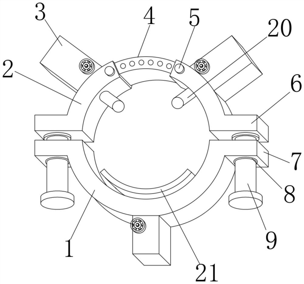
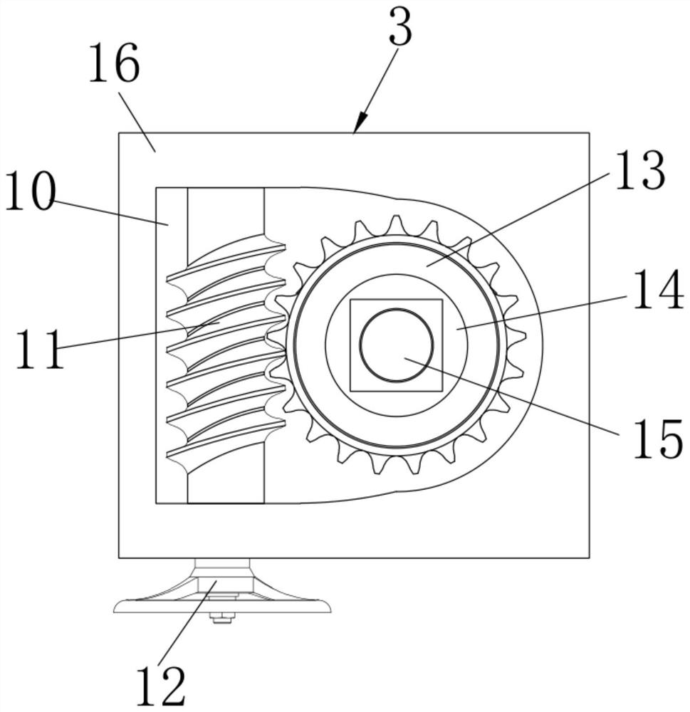
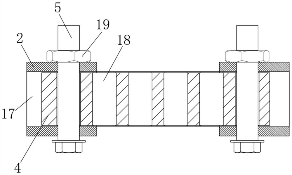
The invention discloses a clamping device for automatic equipment part machining. The clamping device comprises a carrier ring and a stringing ring. A clamping carrier ring is arranged on the inner side of the carrier ring. A clamping head is arranged on the inner side of the stringing ring. Pushing mechanisms are arranged on the outer side of the carrier ring and the outer side of the stringing ring correspondingly. Each pushing mechanism comprises a clamping base, wherein a pushing groove is formed in the clamping base, a worm is connected to one end of the inner side of the pushing groove in a rotating manner through a bearing, a pushing nut is connected to the other end of the inner side of the pushing groove through a bearing in a rotating manner, and a turbine is fixedly connected tothe outer side of the pushing nut. According to the clamping device, by designing the pushing mechanisms, the clamping head and the clamping carrier ring, when the device is used, the pushing mechanisms push the clamping head and the clamping carrier ring to position and clamp an automatic equipment part, by means of transmission of the worms and the turbines, after a drive hand wheel drives pushing screw rods to move, self-locking can be achieved, and thus the phenomenon that due to stress self-rotation, clamping is not stable is prevented.

Description

technical field [0001] The invention relates to the technical field of processing automation equipment parts, in particular to a clamping device for processing automation equipment parts. Background technique [0002] Automation technology is widely used in industry, agriculture, military, scientific research, transportation, commerce, medical care, services and households. The use of automation technology can not only liberate people from heavy physical labor, part of mental work, and harsh and dangerous working environments, but also expand human organ functions, greatly improve labor productivity, and enhance human ability to understand and transform the world. . [0003] When the existing clamping device for processing parts of automation equipment is in use, it will be unstable due to the limitation of the device, causing the parts of automation equipment to shake when it is fixed. Therefore, it is urgent to design an automatic Equipped with a clamping device for part...

Claims


Application Information

Patent Timeline
Patent Type & Authority Applications(China)
IPC IPC(8): B25B11/00
CPCB25B11/00
Inventor 周洁
Owner 周洁
Learn More