
Arch frame clamping manipulator

The technology of a manipulator and an arch frame is applied in the field of arch frame clamping manipulators, which can solve the problems of small swing force arm and complicated clamping method of the clamping device, achieve simple structure of the clamping device, reduce the cylinder diameter of the oil cylinder, and reduce the pressure of the oil cylinder. Effect

Pending Publication Date: 2020-08-21
HUNAN PENGXIANG XINGTONG AUTOMOBILE CO LTD
View PDF2 Cites 4 Cited by
  • Summary
  • Abstract
  • Description
  • Claims
  • Application Information

AI Technical Summary

Problems solved by technology

[0004] Another example is patent CN201611208626 which discloses an adjustable corner arch clamping mechanism. The clamping method of this scheme is relatively complicated, and the swing arm of the clamping device is small.

Method used


Image

  • Arch frame clamping manipulator
  • Arch frame clamping manipulator
  • Arch frame clamping manipulator

Examples


Embodiment Construction

[0025] The accompanying drawings are for illustrative purposes only, and should not be construed as limitations on this patent; in order to better illustrate this embodiment, certain components in the accompanying drawings will be omitted, enlarged or reduced, and do not represent the size of the actual product; for those skilled in the art It is understandable that some well-known structures and descriptions thereof may be omitted in the drawings. The positional relationship described in the drawings is for illustrative purposes only, and should not be construed as a limitation on this patent.

[0026] In the drawings of the embodiments of the present invention, the same or similar symbols correspond to the same or similar components; The orientation or positional relationship indicated by etc. is based on the orientation or positional relationship shown in the drawings, and is only for the convenience of describing the present invention and simplifying the description, rathe...


PUM


Abstract

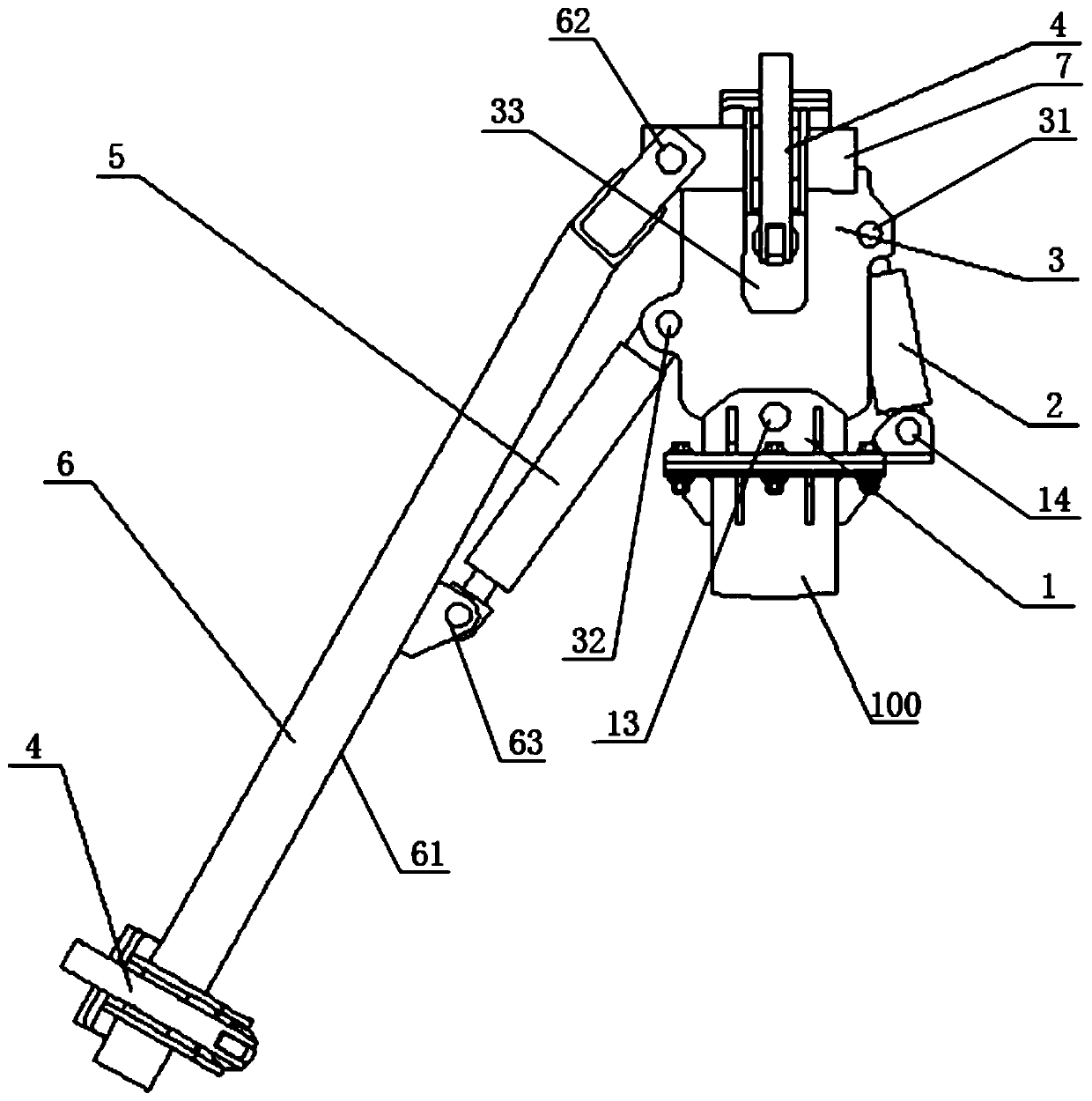
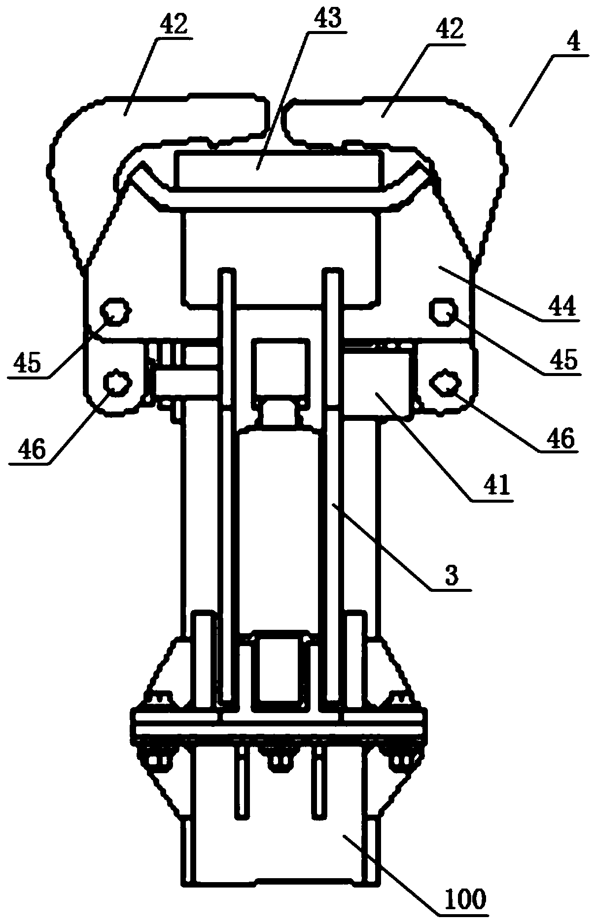
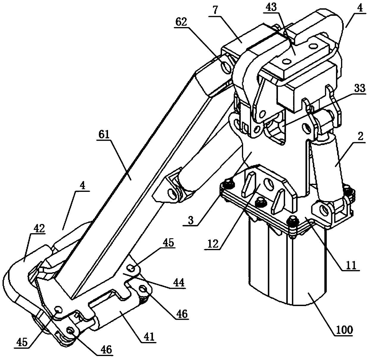
The invention relates to the technical field of engineering machinery, particularly to an arch frame clamping manipulator. The arch frame clamping manipulator comprises a clamping body, two clamping devices for clamping an arch frame, an auxiliary arm and an auxiliary arm swing cylinder; the clamping body is hinged to one end of the auxiliary arm swing cylinder, and the auxiliary arm is hinged tothe other end of the auxiliary arm swing cylinder; one end of the auxiliary arm is hinged to the upper part of the clamping body, and one of the clamping devices is fixedly arranged at the other end of the auxiliary arm; and the other clamping device is fixed on the upper part of the clamping body. According to the arch frame clamping manipulator, the two-point clamping of the arch frame is achieved, the clamping manipulator fits the arch frame well, and at the same time, the angle and posture of the arch frame are convenient to adjust.

Description

technical field [0001] The present invention relates to the technical field of engineering machinery, and more specifically, to an arch clamping manipulator. Background technique [0002] At present, when the clamping device clamps the tunnel arch frame, it clamps one point unstable. When clamping two points, the two clamping points cannot be effectively and fully fitted. The range of clamping positions is narrow, and the platform of the hanging platform is separated from the mechanical arm frame. [0003] For example, patent CN201821070082 discloses a grabbing device for tunnel arches. One end of the clamping part of this solution uses a rack and pinion, which is inconvenient, and there is a sense of frustration during the clamping process, and there is a possibility that the clamping will not be tight. The short distance between the two clamping points is not conducive to the stability of the arch. The middle position of the arch needs to be clamped, and the clamping devi...

Claims


Application Information

Patent Timeline
IPC IPC(8): B25J15/00B25J15/08
CPCB25J15/00B25J15/08B25J15/0052
Inventor 胡鹏填苏早魏鹏程
Owner HUNAN PENGXIANG XINGTONG AUTOMOBILE CO LTD
Learn More