Clamp and robot applicable to clamp

A clamp and splint technology, applied in the field of clamps and their applicable robots, can solve the problems of being easily stuck, the splint is not stable, and the device is easy to fall, so as to prevent the device from falling, reduce manual labor, and improve work. The effect of efficiency

Pending Publication Date: 2019-06-14
GREE ELECTRICHEFEI +1
View PDF1 Cites 2 Cited by
  • Summary
  • Abstract
  • Description
  • Claims
  • Application Information

AI Technical Summary

Problems solved by technology

The splint of this invention patent is not stable, and it is easy to get stuck, and it is easy to fall when clamping heavier components

Method used


Image

  • Clamp and robot applicable to clamp
  • Clamp and robot applicable to clamp
  • Clamp and robot applicable to clamp

Examples


Embodiment Construction

[0032] The present invention will be described in detail below in conjunction with the accompanying drawings, so as to facilitate those skilled in the art to understand the present invention, and does not constitute a limitation to the present invention.

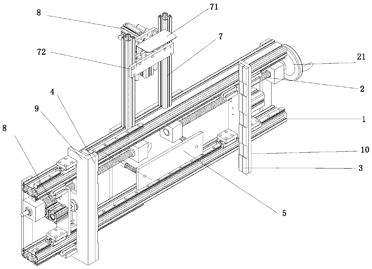
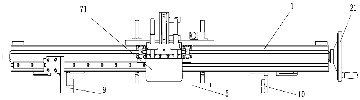
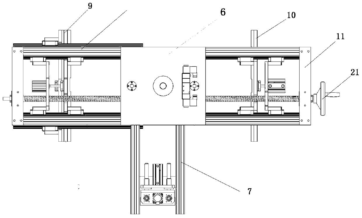
[0033] as the picture shows, figure 1 It is an overall structural diagram of a preferred embodiment of the present invention, figure 2 , 3 respectively figure 1 top and front views of the Figure 4 for image 3 As can be seen from the figure, the fixture includes: a mounting bracket, the mounting bracket used in this embodiment is two parallel profile brackets 1, the two ends of the two profile brackets 1 are connected by a connecting plate 11, the connection The plate 11 is clamped on the profile bracket 1 and can move along the profile bracket 1; a screw 2 is arranged on the mounting bracket, the screw here is two-stage, and one end of the left screw is fixed on the connecting plate 11, The other end is fixed on the ...


PUM


Abstract

The invention relates to the field of mechanical equipment, in particular to a clamp and a robot applicable to the clamp. The clamp comprises a mounting bracket, screw rods and at least one set of clamp assemblies, wherein the screw rods are arranged on the mounting bracket, and the clamp assemblies are arranged on the mounting bracket; and each set of the clamp assemblies comprises two clamping plates and a driving assembly, wherein the clamping plates are arranged on the mounting bracket, at least one clamping plate is connected to the screw rods so that the clamping plate can move through rotation of the screw rods, and the clamping plates are in a clamping state or in a loosened state through the driving assembly. According to the clamp, clamping is firm, the clamping efficiency is improved, the product rejection rate is reduced, and the labor intensity of workers is reduced.

Description

technical field [0001] The invention relates to the field of mechanical equipment, in particular to a clamp and an applicable robot. Background technique [0002] During the production of tube expansion, employees need to manually carry the two parts to the tube expander. The average weight of the two parts is about 10Kg, and the daily production volume is about 800 pieces. The labor intensity of the employees is very high, resulting in unstable equipment operators and high turnover rate. Therefore, the use of mechanical fixtures to automatically take the two parts, transport them to the tube expander, install the material on the tube expander, remove the two parts after the expanded tube from the equipment, transport them to the material area, and reduce the labor intensity is an urgent problem to be solved. . The patent with publication number CN206605513 discloses an industrial robot fixture for machining used on industrial robots, including a fixed block, a through hole...

Claims


Application Information

Patent Timeline
Patent Type & Authority Applications(China)
IPC IPC(8): B25J15/00B21D43/00
Inventor 陈顺田振何刚金柱友颜日生董杰张传旺王中超时春谢传波
Owner GREE ELECTRICHEFEI
Why Eureka
Try Eureka