Eureka AIR delivers breakthrough ideas for toughest innovation challenges, trusted by R&D personnel around the world.

Water-sealed tank

A water-sealing tank and water-sealing technology, applied in valve devices, mechanical equipment, engine components, etc., can solve problems such as fluctuation of sealing water, inability of sealing water to play a sealing role, and large-pulse combustion of torches, so as to reduce the water sealing level difference. Effect

Inactive Publication Date: 2020-12-08
SINOPEC GUANGZHOU ENG +1
View PDF6 Cites 0 Cited by
  • Summary
  • Abstract
  • Description
  • Claims
  • Application Information

AI Technical Summary

Problems solved by technology

[0003] The purpose of the present invention is to provide a water-sealed tank to solve the problem that the existing water-sealed tank uses a flare exhaust gas inlet pipe and a water seal height to cause the flare exhaust gas to discharge gas from the flare in a large pulse form The bottom outlet of the inlet pipe flows out, causing the sealing water to fluctuate violently due to the impact, causing the torch to burn in large pulses, and the sealing water cannot play a sealing role, etc.

Method used


Image

  • Water-sealed tank
  • Water-sealed tank
  • Water-sealed tank

Examples


Embodiment Construction

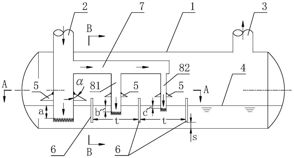
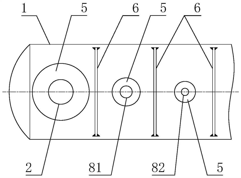
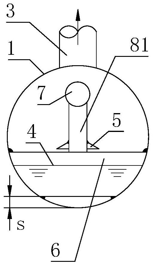
[0016] see figure 1 , figure 2 and image 3 , A water-sealed tank of the present invention is provided with a horizontal tank body 1, and the two ends of the horizontal tank body 1 are respectively provided with a main pipe 2 for the inlet of the torch exhaust gas and a pipeline 3 for the outlet gas of the torch exhaust gas. The main pipeline 2 of the flare exhaust gas inlet is arranged vertically, and the top inlet is connected with the process device. The outlet of the flare exhaust gas outlet pipeline 3 is connected with the flare. The bottom of the horizontal tank body 1 is equipped with sealing water, the upper surface of the sealing water is the sealing water liquid level 4, and the top of the sealing water liquid level 4 is the gas phase space.

[0017] Horizontal tank body 1 is provided with an auxiliary pipe main pipe 7 along the axial direction of horizontal tank body 1, one end of auxiliary pipe main pipe 7 is connected with main pipe 2 of flare exhaust gas inle...


PUM


Abstract

The invention discloses a water-sealed tank. The water-sealed tank is provided with a horizontal tank body (1), and a torch exhaust gas inlet main pipeline (2) and a torch exhaust gas outlet pipeline(3) are arranged on the horizontal tank body. One or more auxiliary pipelines are arranged on an auxiliary pipeline main pipe (7) in the horizontal tank body along the axial direction of the horizontal tank body. The diameter of the auxiliary pipeline adjacent to the torch exhaust gas inlet main pipeline and the depth of the bottom outlet immersed into sealing water in the horizontal tank body arerespectively smaller than the diameter of the torch exhaust gas inlet main pipeline and the depth of the bottom outlet immersed into the sealing water. When more than one auxiliary pipeline is arranged, between two adjacent auxiliary pipelines, the diameter of the auxiliary pipeline far away from the torch exhaust gas inlet main pipeline and the depth of the bottom outlet immersed in the sealingwater are respectively smaller than the diameter of the auxiliary pipeline close to the torch exhaust gas inlet main pipeline and the depth of the bottom outlet immersed in the sealing water. The water-sealed tank provided by the invention can be used for petrochemical enterprises.

Description

technical field [0001] The invention relates to a water-sealed tank used in a flare system in a petrochemical enterprise. Background technique [0002] The torch systems of petrochemical enterprises often use water-sealed tanks and liquid seals to prevent the torch system from flashing back, avoid damage to the discharge pipe network of the torch system and its connected equipment, and ensure production safety. The existing commonly used water-sealed tank is provided with a horizontal tank body, which is provided with a torch exhaust gas inlet pipeline and a torch exhaust gas outlet pipeline, and the bottom of the horizontal tank body is equipped with sealing water. The existing problem is that the flare gas inlet pipe is one, and its bottom outlet is immersed in the sealing water to a certain depth to form a water seal with a certain height. When the process unit is in shutdown and accident conditions, a large amount of flammable flare exhaust gas will be discharged to the...

Claims


Application Information

Patent Timeline
Patent Type & Authority Applications(China)
IPC IPC(8): F16K13/10
CPCF16K13/10
Inventor 程继元梁文凯
Owner SINOPEC GUANGZHOU ENG
Why Eureka
Eureka Blog
Learn More