
A device and method for measuring deformation of large components in a closed heating furnace

A technology for measuring devices and large components, applied in measuring devices, instruments, etc., can solve problems such as difficulty in application, image distortion, high-temperature furnace structure, heat insulation and airtight design difficulties, and achieve high feasibility, improve measurement accuracy, and operate simple effect

Active Publication Date: 2021-09-03
YANSHAN UNIV
View PDF8 Cites 0 Cited by
  • Summary
  • Abstract
  • Description
  • Claims
  • Application Information

AI Technical Summary

Problems solved by technology

High-temperature extensometers are commonly used in contact measurement to measure the deformation within the gauge length of the specimen, but due to the high-temperature environment, the usual fixing methods (gluing, clamping, binding, etc.) between the extensometer’s extensometer and the specimen are difficult to apply; in addition, In order to ensure the normal operation of the extensometer, the side furnace wall of the high temperature furnace is often opened, only the extension arm is placed in the furnace, and the sensing and measuring part is placed outside the furnace, which brings difficulties to the heat insulation and sealing design of the high temperature furnace
Non-contact measurement mainly includes methods such as speckle technology, moiré, and laser extensometer. Changes in the refractive index will cause image distortion, greatly affecting the accuracy of image acquisition and calculation; Furnace structure, heat insulation and airtight design bring difficulties

Method used


Image

  • A device and method for measuring deformation of large components in a closed heating furnace
  • A device and method for measuring deformation of large components in a closed heating furnace
  • A device and method for measuring deformation of large components in a closed heating furnace

Examples


Embodiment Construction

[0026] In order to more clearly illustrate the technical solutions in the embodiments of the present invention or the prior art, the following will briefly introduce the drawings that need to be used in the description of the embodiments or the prior art. Obviously, the accompanying drawings in the following description These are some embodiments of the present invention. Those skilled in the art can also obtain other drawings based on these drawings without creative work.

[0027] It should be noted that in the description of the present invention, it should be noted that the terms "upper", "lower", "top", "bottom", "one side", "another side", "left", " The orientation or positional relationship indicated by "right", etc. is based on the orientation or positional relationship shown in the drawings, and is only for the convenience of describing the present invention and simplifying the description, and does not mean that the device or element must have a specific orientation, b...


PUM


Abstract

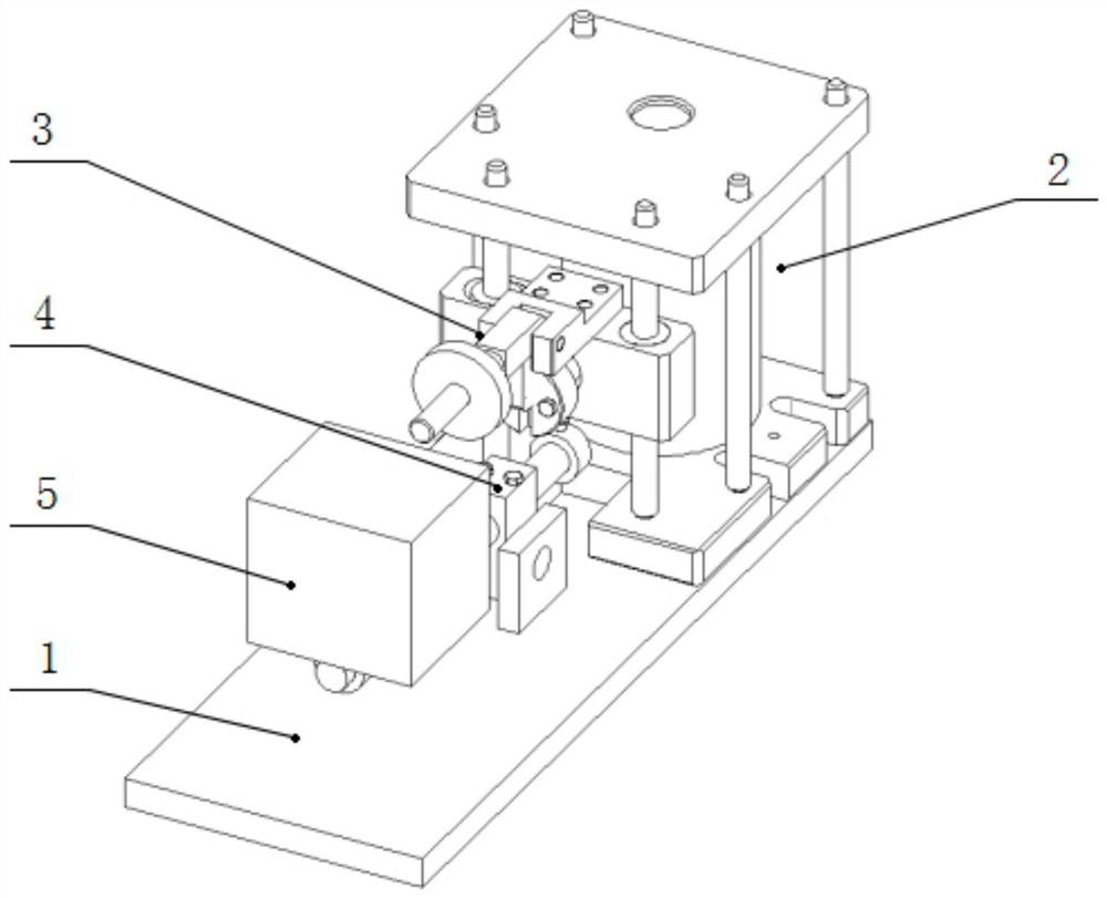
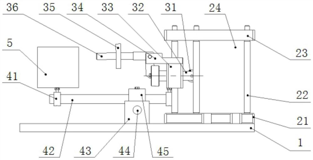
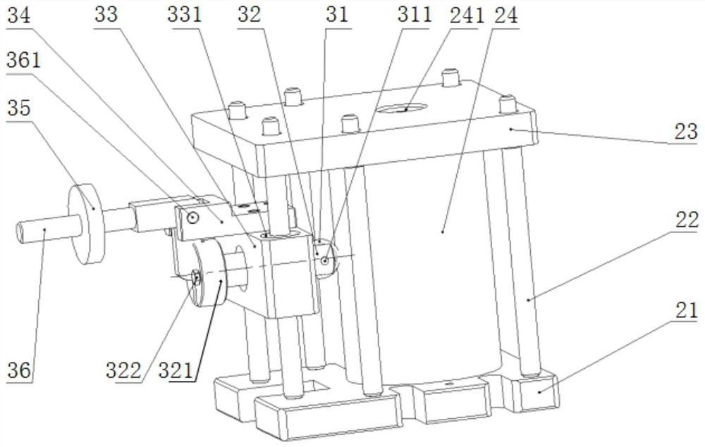
The invention relates to a large component deformation measurement device in a closed heating furnace and a method thereof. The device includes a large base plate, a sensing assembly, a contact assembly and a lever assembly, and the sensing assembly is fixedly connected to the rear surface of the large base plate. The contact assembly is slidably connected to the front side of the sensing assembly, the lever assembly is fixedly connected to the middle of the large bottom plate, and the rear end of the lever assembly is in contact with the bottom of the contact assembly. The invention adopts a lever structure design, which converts the deformation of the workpiece at high temperature into displacement and transmits it to the sensor. In this way, the deformation measurement is transferred from the high temperature area inside the high temperature furnace to the normal temperature area outside the high temperature furnace, realizing the deformation accuracy of high temperature materials. Quantitative research has improved the measurement accuracy; and the instrument components in the high temperature area are all made of ultra-high temperature resistant materials, which have high reliability.

Description

technical field [0001] The invention relates to the technical field of high-temperature mechanical testing, in particular to a device and method for measuring deformation of large components in a closed heating furnace. Background technique [0002] High-temperature materials and structures in high-tech fields and national defense equipment construction need to withstand complex heat / force / oxidation coupling or complex combustion environments, and due to the complexity of the performance of the materials themselves, the design and service of components used in extreme environments When evaluating safety, it is necessary to grasp the parameters such as deformation and strength of materials in high-temperature oxidizing environment. However, at present, there is no effective method for high-temperature mechanical evaluation at home and abroad, and there is a lack of related instruments and equipment. This is mainly due to the fact that the heating elements, fixtures and sensi...

Claims


Application Information

Patent Timeline
Patent Type & Authority Patents(China)
IPC IPC(8): G01B21/32
CPCG01B21/32
Inventor 张文文刘鑫刚石鑫生杜强袁林
Owner YANSHAN UNIV
Learn More