
Iron cylinder stamping forming equipment

A stamping forming, cylinder technology, applied in the direction of metal processing equipment, feeding devices, manufacturing tools, etc.

Pending Publication Date: 2020-12-11
付帅帅
View PDF5 Cites 1 Cited by
  • Summary
  • Abstract
  • Description
  • Claims
  • Application Information

AI Technical Summary

Problems solved by technology

[0005] In order to overcome the shortcomings of the existing iron cylinder stamping and forming methods that need to manually place the iron cylinders one by one on the storage table and then stamp and form the iron cylinders, the technical problem to be solved is to provide a method that can realize automatic Iron cylinder stamping and forming equipment that transfers iron cylinders and automatically stamps and forms iron cylinders

Method used


Image

  • Iron cylinder stamping forming equipment
  • Iron cylinder stamping forming equipment
  • Iron cylinder stamping forming equipment

Examples


Embodiment 1

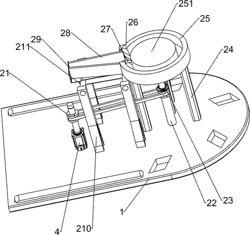
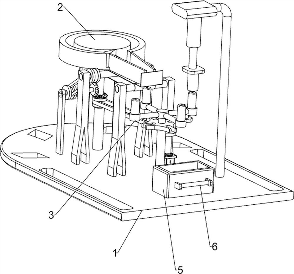
[0020] One kind of cylindrical iron press-molding apparatus, such as figure 1 Shown, it comprises a bottom plate 1, the transfer mechanism 2, pressing mechanism 3, 4, 5 and lever 6 collecting box, a rear top plate conveying means 2 is provided with a servo motor, the base plate 1 is provided with a top front side of the press means 3, punching means transfer mechanism member 3 is connected to the member 2, the base plate 4 is provided with a top in the middle, is connected to an output shaft of the servo motor member 4 and the transport mechanism 2, the intermediate side plate is placed on top a front frame 5 collected, the collection box servomotor 5 the front portion 6 is provided with pull rod.

[0021] When people need a cylindrical iron press-molding, it is first placed on a cylindrical iron member conveying mechanism 2, the collection box 5 is placed in the front side of the top plate 1, and then it starts the servo motor and the press mechanism 4 member 3, the output shaft ...

Embodiment 2

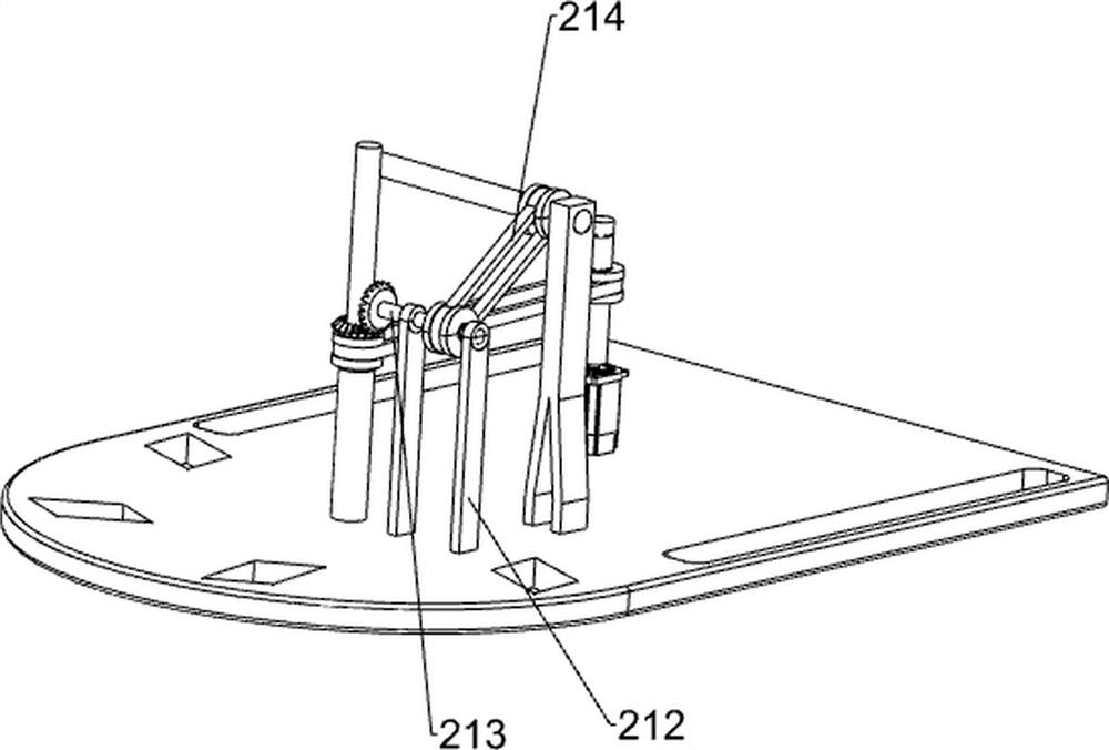
[0023] On the basis of Example 1 above, such as Figure 2-4 , The transfer mechanism 2 includes a first transport assembly 21, shaft 22, bevel gear set 23, a first support column 24, a support table 25, the turntable 251, the wedge block 26, the push rod 27, the guide plate 28, L-shaped stopper plate 29, bearing housing 210, the second transfer assembly 211, holder 212, the pawl 213 and the third transport assembly 214, a rear side of the top plate intermediate rotary shaft 22 is connected between the shaft 22 and the output shaft of the servo motor 4 connected with a first transport assembly 21, the base plate 1 is provided with a uniform top left rear bracket 212, the bracket 212 is the number 2, between the rotary bracket 212 is connected to the pawl 213, the shaft 213 and the right side of the pawl 22 between the bevel gear set 23 is connected to the base plate 1 is provided with a first intermediate top rear support column 24, support post 24 is located at the rear side of the...


PUM


Abstract

The invention relates to stamping forming equipment, in particular to iron cylinder stamping forming equipment. According to the iron cylinder stamping forming equipment, an iron cylinder can be automatically conveyed, and stamping forming can be automatically conducted on the iron cylinder. The iron cylinder stamping forming equipment comprises a bottom plate, a conveying mechanism, a stamping mechanism, a servo motor, a collecting frame and a pull rod. The conveying mechanism is arranged on the rear side of the top of the bottom plate; the stamping mechanism is arranged on the side, away from the conveying mechanism, of the top of the bottom plate; components of the stamping mechanism are connected with components of the conveying mechanism; the servo motor is arranged in the middle of the top of the bottom plate; an output shaft of the servo motor is connected with components of the conveying mechanism; the collecting frame is placed on the side, close to the servo motor, of the topof the bottom plate; and the pull rod is arranged at the end, away from the servo motor, of the collecting frame. Under the cooperation of the servo motor, the conveying mechanism and the stamping mechanism, iron cylinders can be automatically conveyed to a storage table, and the iron cylinders which are not formed are subjected to stamping forming.

Description

Technical field [0001] The present invention relates to a press molding apparatus, particularly to a cylindrical iron press molding apparatus. Background technique [0002] Iron cylinder is in our daily lives often see filled container, such as iron tea box, iron cans and cigarette boxes, when iron cylinder during production, often need to iron cylinder press-molding, whereby the iron cylinder of burring. [0003] The method of the conventional cylindrical iron press forming, it is a non-press-molded iron cylinder was placed underneath the glove pressing device table, and then the pressing mechanism for pressing a cylindrical iron molding, and then it was followed by press-molding a cylindrical iron extraction, this method requires people to manually set one by one in a cylindrical iron glove stage, which is inefficient cylindrical iron press forming. [0004] It is necessary to develop a ferrous can automatically transfer cylinder and cylindrical iron automatic stamping device f...

Claims


Application Information

Patent Timeline
IPC IPC(8): B21D22/08B21D43/02B21D43/04B21D43/12
CPCB21D22/08B21D43/026B21D43/04B21D43/12
Inventor 付帅帅
Owner 付帅帅
Learn More