
A Bottom Steel Seal Sealing Device for Building a Lamp

A technology of stencil and chassis, applied in the field of bottom stencil-stamping devices for building lamps, can solve the problems of cumbersome operation process, low work efficiency, manpower consumption, etc., and achieve the effects of simple operation, improved work efficiency and manpower saving.

Active Publication Date: 2022-05-13
林振新
View PDF5 Cites 0 Cited by
  • Summary
  • Abstract
  • Description
  • Claims
  • Application Information

AI Technical Summary

Problems solved by technology

[0006] In order to overcome the disadvantages of the above method, such as cumbersome operation process, low work efficiency, and relatively labor-intensive operation, the technical problem to be solved by the present invention is to provide a construction that is simple to operate, can improve work efficiency, and saves manpower. Bottom stamping device for cups

Method used


Image

  • A Bottom Steel Seal Sealing Device for Building a Lamp
  • A Bottom Steel Seal Sealing Device for Building a Lamp
  • A Bottom Steel Seal Sealing Device for Building a Lamp

Examples


Embodiment 1

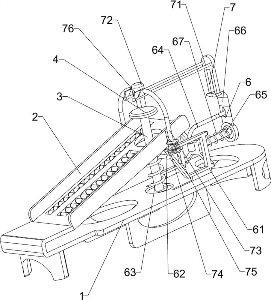
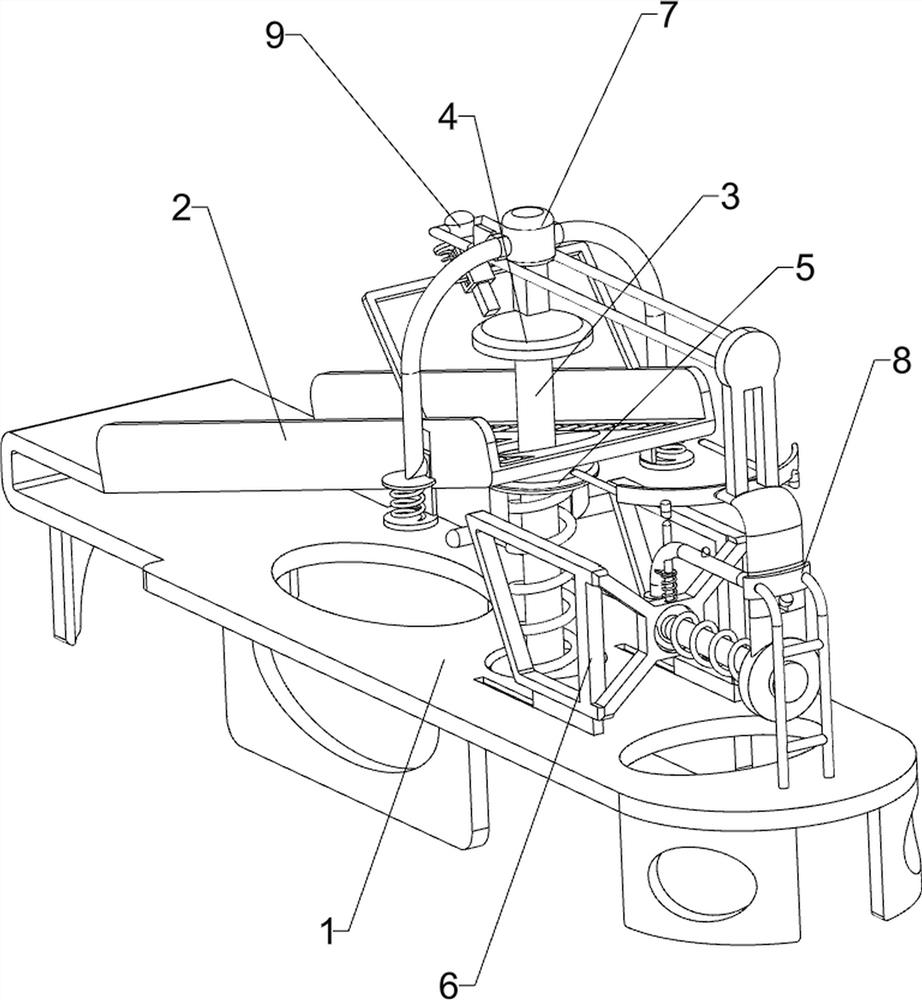
[0023] A bottom steel stamping device for building a lamp, such as Figure 1-2 As shown, it includes a chassis 1, a guide frame 2, a vertical slide bar 3, a placement plate 4, and a limit plate 5. The guide frame 2 is connected to the top and rear side of the chassis 1, and the vertical slide bar 3 is slidably connected to the front side of the top of the chassis 1. , the top of the vertical slide bar 3 is connected with a placement plate 4, the upper part of the vertical slide bar 3 is connected with a limit plate 5, and also includes a drive mechanism 6 and a stamp mechanism 7, and a drive mechanism 6 is arranged between the chassis 1 and the limit plate 5, and the drive A stamp mechanism 7 is provided between the mechanism 6 and the guide frame 2 .

[0024] Driving mechanism 6 comprises transmission seat 61, the first push rod 62, back-moving spring 63, guide rod 64, cross bar 65, push block 66 and limit spring 67, and chassis 1 top front side slide type is connected with t...

Embodiment 2

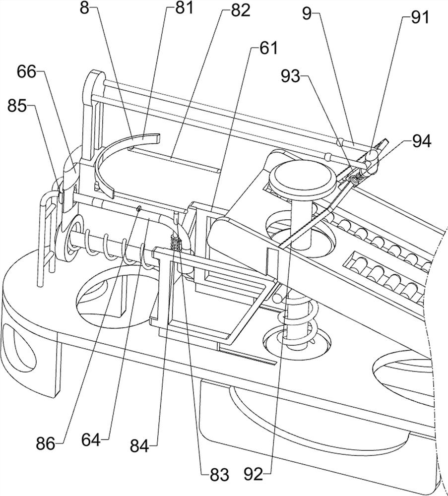
[0028] On the basis of Example 1, such as image 3 As shown, a conveying mechanism 8 is also included, and the conveying mechanism 8 includes an arc-shaped push plate 81, a clamping rod 82, a vertical rod 83, a projection 86, a compression spring 84 and a clamping plate 85, and the rear side of the pushing block 66 is connected with an arc-shaped Push plate 81, arc-shaped push plate 81 bottom left and right sides are all connected with clamping bar 82, drive seat 61 top is connected with vertical bar 83, vertical bar 83 and guide bar 64 sliding fit, guide bar 64 is connected with drive seat 61 Compression spring 84 is arranged, and compression spring 84 is sleeved on the vertical bar 83, and guide bar 64 top is connected with bump 86, and bump 86 cooperates with pushing block 66, and chassis 1 top front side is connected with clamping plate 85, and clamping plate 85 and guide Rod 64 fits.

[0029] When placing the built-in cup, the built-in cup can be placed between the arc-s...


PUM


Abstract

The invention relates to a stamping device, in particular to a bottom steel seal stamping device for building a cup. The technical problem to be solved by the present invention is how to design a bottom steel seal stamping device for building a cup that is easy to operate, can improve work efficiency, and saves manpower. In order to solve the above-mentioned technical problems, the present invention provides such a bottom steel seal stamping device for building a lamp, which includes: a chassis, a guide frame connected to one side of the top; The top of the slide bar is connected with a placement plate; the limit plate is connected to the upper part of the vertical slide bar; the drive mechanism is arranged between the chassis and the limit plate; the seal mechanism is arranged between the drive mechanism and the guide frame. The present invention seals the Jianzhan through the cooperative operation of the driving mechanism and the seal mechanism, thereby achieving the effect of sealing the Jianzhan.

Description

technical field [0001] The invention relates to a stamping device, in particular to a bottom steel seal stamping device for building a cup. Background technique [0002] Jianzhan mostly has a large mouth and small bottom, and some are shaped like a funnel; most of them are ring feet and the ring feet are relatively shallow, the heel of the feet is often trimmed (commonly known as chamfering), and the soles of the feet are slightly inclined; a few are solid feet (mainly small round bowls). The shape is simple and vigorous, and the hand feel is generally heavy. Jianzhan is divided into four categories: open mouth, skimming mouth, closed mouth and beam mouth, each category is divided into large, medium and small; small round bowls are classified into small closed mouth bowls. When Jianzhan is made, it is usually stamped on its side and bottom. [0003] At present, the way of stamping the Jianzhan is usually to place the Jianzhan manually first, then align the seal with the J...

Claims


Application Information

Patent Timeline
Patent Type & Authority Patents(China)
IPC IPC(8): B41K3/36
CPCB41K3/36
Inventor 林振新
Owner 林振新
Learn More