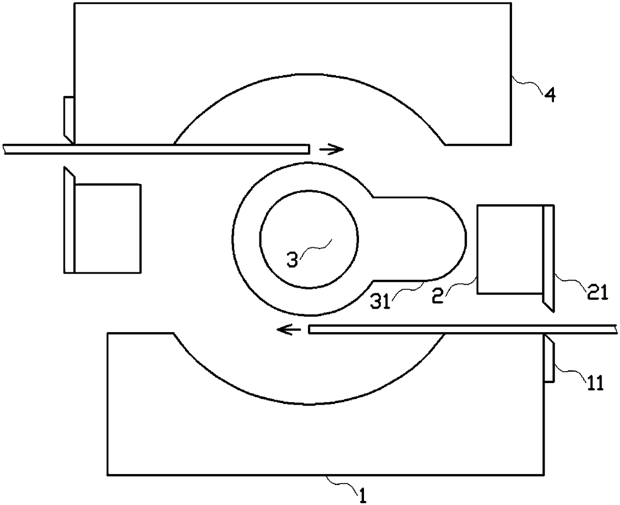
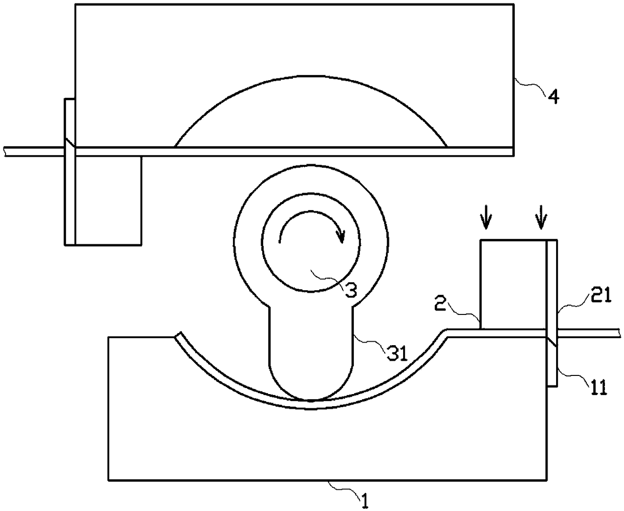
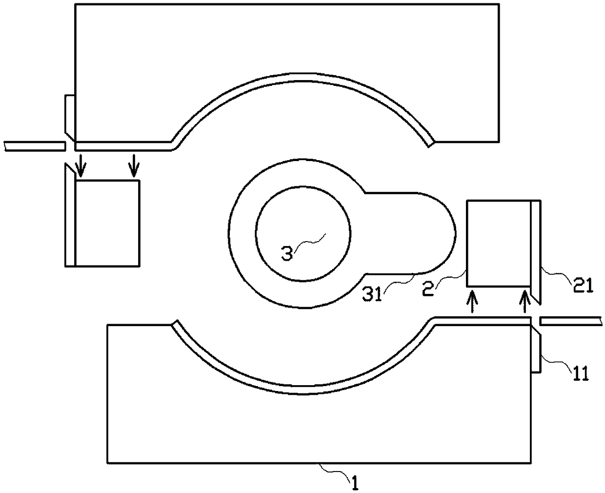
[0013] Below in conjunction with accompanying drawing and embodiment, the present invention is further described:
[0014] like figure 1 , figure 2 , image 3 As shown in the middle embodiment, the cam type continuous stamping die is a process that can realize the stamping process of the workpiece to be processed after the rotating stamping rod rotates, and can realize the continuous feeding, cutting, stamping and blanking operations. The punching efficiency is high, and no manual operation is required, which greatly reduces the time required for punching. It includes a forming module 1, a cutting module 2 and a rotating shaft module 3; The opposite surfaces of the molds are provided with forming curved surfaces of the same shape; the feeding directions of the symmetrical forming modules 1 are opposite, and a fixed cutting knife 11 is provided on the side of the feeding end of the forming module 1, and the edge of the fixed cutting knife 11 is The front and rear are opposite to each other; the cutting module 2 includes a sliding block that slides back and forth, and a sliding cutter 21 is arranged on the sliding block. The sliding block is driven by a pushing device; the rotating shaft module 3 includes a punching rod 31, and the end face of the punching rod 31 is an arc surface; the punching rod 31 is rotatably assembled on a rotating shaft driven by a rotating motor, The axis of the rotating shaft is consistent with the center of the curved surface formed by the forming module 1; the distance between the punching rod 31 and the arc-shaped surface during punching is consistent with the thickness of the workpiece to be punched.
[0015] When the cam-type continuous stamping die is in use, the sheet workpiece to be processed is placed at the feeding end of the forming module 1, and moves along the side of the forming curved surface in the forming module 1; when the sheet workpiece moves to the desired position, start In the cutting module 2, the sliding block slidingly drives the sliding cutter 21 to slide to the position of the fixed cutter 11; when the sliding cutter 21 is in contact with the fixed cutter 11, the sheet workpiece is cut off At the same time, the sliding block compresses the front end of the sheet workpiece, which plays a role in positioning the sheet workpiece; when the sheet workpiece is determined, the rotating shaft module 3 is activated, and the rotating shaft module 3 rotates to drive the punching rod 31 Rotate, so that the end face of the punching rod 31 is in contact with the sheet workpiece, and at the same time the sheet workpiece is punched to deform it; Press down and be punched into the desired shape to achieve the effect of punching. Since the forming module 1 is a set of front-to-back symmetrical female dies, the female dies are symmetrical with respect to the center of the rotating shaft module 3, so after the rotating shaft module 3 rotates once, the sheet workpiece on the female dies can be The stamping process is completely completed, that is, the stamping of two workpieces is completed in one stamping process, which shortens the time required for stamping and improves stamping efficiency. After the stamping is completed, the cutting module 2 is reset, the sliding block is reset and sliding, and the workpiece falls and separates from the forming module 1 under the action of gravity, so as to achieve the effect of demoulding.
[0016] like Figure 4 As shown in the figure, a fixing block 22 is arranged behind the sliding block, a magnetic material is arranged on the side of the sliding block facing the fixing block 22, and a side of the fixing block 22 facing the sliding block is arranged with a magnetic material. An electromagnet; the sliding block and the fixed block 22 are connected by a tension spring 23; the electromagnet is connected to a power supply through a control circuit. The electromagnet structure connected by the control circuit can be turned on and off at the same time, so that the cutting module 2 can slide at the same time, so that the sheet workpieces on both sides can be cut at the same time, ensuring the uniformity of the cut size of the sheet workpieces At the same time, the cutting module 2 can position the sheet workpiece, so that the rotating shaft module 3 can ensure the integrity of punching during punching; in addition, this structure has the characteristics of simple structure and low cost.
[0017] like figure 1 , figure 2 , image 3 As shown, a heating module is arranged on the sliding block, and the heating module is in contact with the rear side of the blade of the sliding cutter 21 through a heat-conducting sheet, and the sliding cutter 21 and the fixed cutter 11 are made of metal materials . When the sliding cutter 21 is in contact with the sheet workpiece, since the heating module is provided on it, the heating module can heat the sliding cutter 21 to a certain extent, so that the sliding cutter 21 can be more easily The thin workpiece is truncated, and at the same time, the truncated surface of the thin workpiece does not appear incompletely truncated, which is beneficial to the subsequent demoulding operation.
[0018] like figure 1 , figure 2 , image 3 As shown, the end of the punching rod 31 is set as a separate end, the end of the punching rod 31 and the punching rod 31 are connected by a telescopic rod, and a locking device is provided on the telescopic rod; The end of the punching rod 31 is provided with an electric heating module. Since the length of the end of the punching rod 31 can be adjusted through the telescopic rod, it can be adjusted appropriately according to the thickness of the sheet workpiece, and the sheet workpiece of any thickness can be punched, avoiding the need to replace the punching rod 31 size tedious operation; in addition, the electric heating module on the telescopic rod can soften the sheet workpiece to a certain extent during stamping, so that the stamping process is smoother.
[0019] The above description is only a preferred mode of the present invention, and is not intended to limit the present invention. Any modification, equivalent replacement, improvement, etc. made within the spirit and principle of the present invention shall be included in the protection scope of the present invention. within.