Method and equipment for welding plastic tube network

A welding method and welding equipment technology are applied to the welding method of plastic pipe network and the field of special equipment thereof, which can solve the problem of low mechanical load capacity of plastic pipe network, weak connection at the welding point of thin pipe and collecting pipe, easy deformation of plastic pipe network, etc. problems, to achieve the effect of improving the success rate of welding, improving welding efficiency, and improving mechanical bearing capacity

Inactive Publication Date: 2010-10-20
芶珍
View PDF3 Cites 9 Cited by
  • Summary
  • Abstract
  • Description
  • Claims
  • Application Information

AI Technical Summary

Problems solved by technology

[0003] The object of the present invention aims at the defects that the plastic pipe network is easily deformed during the welding process in the prior art welding plastic pipe network method, and the connection between the thin tube and the collecting pipe is not firm, re

Method used


Image

  • Method and equipment for welding plastic tube network
  • Method and equipment for welding plastic tube network
  • Method and equipment for welding plastic tube network

Examples


Embodiment Construction

[0026] Below in conjunction with accompanying drawing and embodiment the present invention will be further described:

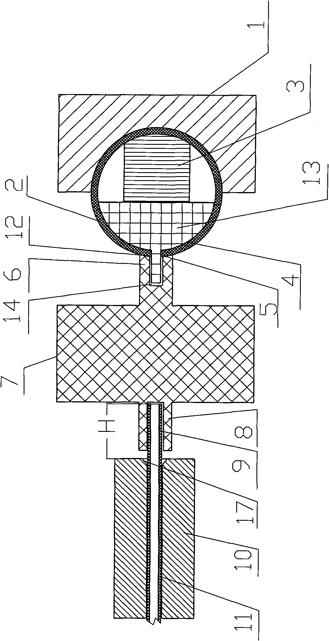
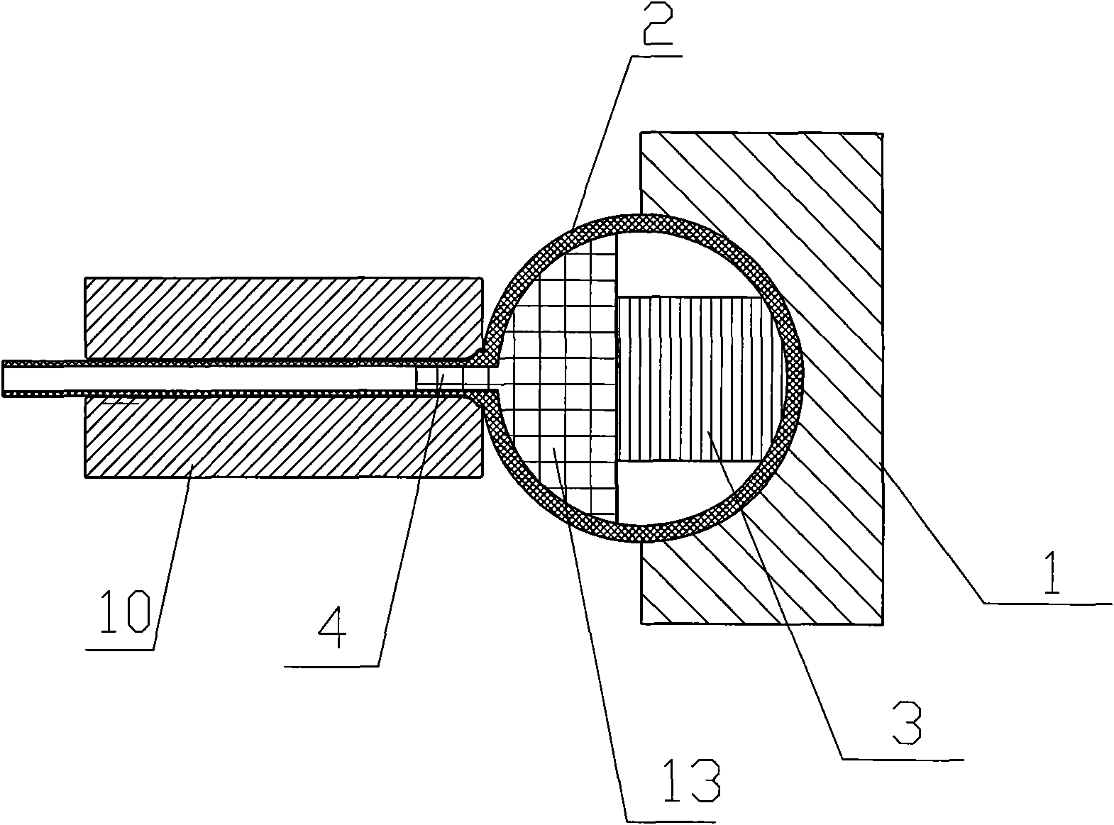
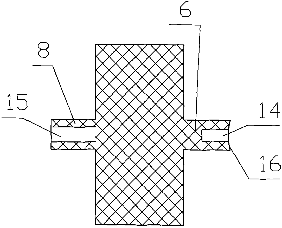
[0027] Such as figure 1 As shown in -5, when manufacturing the plastic pipe network, use special welding equipment to weld the collecting pipe 2 and the thin pipe 11. The welding equipment is at least composed of the following parts: hole forming positioning device, conveying device and heating device. The hole positioning device consists of two parts, one part is the hole-forming thimble liner 4, and the hole-forming thimble liner 4 is provided with needle-shaped protrusions 18 on the strip plate 13 that match the number, shape and position of the bifurcated holes 5. The other part is the positioning strip 3, the length of the positioning strip 3 and the hole-forming thimble strip 4 is equal to or slightly longer than the length of the manifold 2, and its shape is to extend into the bifurcation when the hole-forming thimble strip 4 After the hole 5, the pos...


PUM


Abstract

The invention relates to a method and equipment for welding a plastic tube network. The device comprises a heating device integrating a first heating element, a second heating element and a pore-forming positioning device comprised of a pore-forming ejector liner for forming a branched pore and a positioning liner for fixing the pore-forming ejector liner in the branched pore, wherein in a welding process, the needle protrusion of the pore-forming ejector is placed in the branched pore of a manifold and the pore-forming ejector liner is positioned by the positioning liner; and meanwhile, the end part of a thin tube and an annular welding area around the branched pore are heated so as to weld the end part of the thin tube with the annular welding area of the manifold together along the radial direction of the manifold through extrusion, and a preset profile is molded by an extrusion mold. When the equipment and the method are used, the bending of the manifold can be corrected and prevented, the success rate of primary welding can be improved, the welding efficiency is improved, the connecting force is improved and the mechanical loading capacity of the plastic tube network can be improved.

Description

technical field [0001] The invention relates to a welding method of a plastic pipe network and welding equipment for welding the plastic pipe network using the method, in particular to a welding method for a plastic pipe network used in a heating or cooling system and its special equipment. Background technique [0002] The plastic pipe network is used in air-conditioning equipment. It is a pipe for the medium to regulate the temperature. It is composed of a collecting pipe and a plastic pipe arranged between the collecting pipes on both sides. When manufacturing the plastic pipe network, the two ends of the thin pipe must be separated It is welded together with the manifold on the corresponding side, and the bifurcation hole reserved on the side wall of the manifold is used as a channel connecting the manifold and the thin tube, which is the welding position of the manifold. The diameter of the thin tube in the plastic pipe network is much smaller than the manifold. For exa...

Claims


Application Information

Patent Timeline
IPC IPC(8): B29C65/18
Inventor 芶珍
Owner 芶珍
Why Eureka
Try Eureka