Automatic locking device for three-piece type hoop flange

An automatic locking and clamping flange technology, which is applied in the direction of pressure vessels, fixed-capacity gas storage tanks, mechanical equipment, etc., can solve a large amount of manpower and time for clamping and locking, and the opening and closing efficiency of the pressure cylinder end cover is not enough Fully reflect other issues, to achieve the effect of improving the degree of safety protection, liberating the labor force, and improving work efficiency

Active Publication Date: 2020-12-11
TIANJIN UNIV
View PDF5 Cites 0 Cited by
  • Summary
  • Abstract
  • Description
  • Claims
  • Application Information

AI Technical Summary

Problems solved by technology

The three-piece clamp flange is generally welded with hinge bolts on the top of the left and right two pieces of clamp flanges, and the three-piece clamp flange is locked by manual tightening of the hinge bolts. The locking gap between the end cover of the cylinder and the flange of the cylinder body is very small, and it takes a lot of manpower and time to complete the snap-in and locking, which leads to the inability to fully reflect the opening and closing efficiency of the pressure cylinder end cover

Method used


Image

  • Automatic locking device for three-piece type hoop flange
  • Automatic locking device for three-piece type hoop flange
  • Automatic locking device for three-piece type hoop flange

Examples


Embodiment Construction

[0014] The specific structure and implementation process of this solution will be described in detail below through specific embodiments and accompanying drawings.

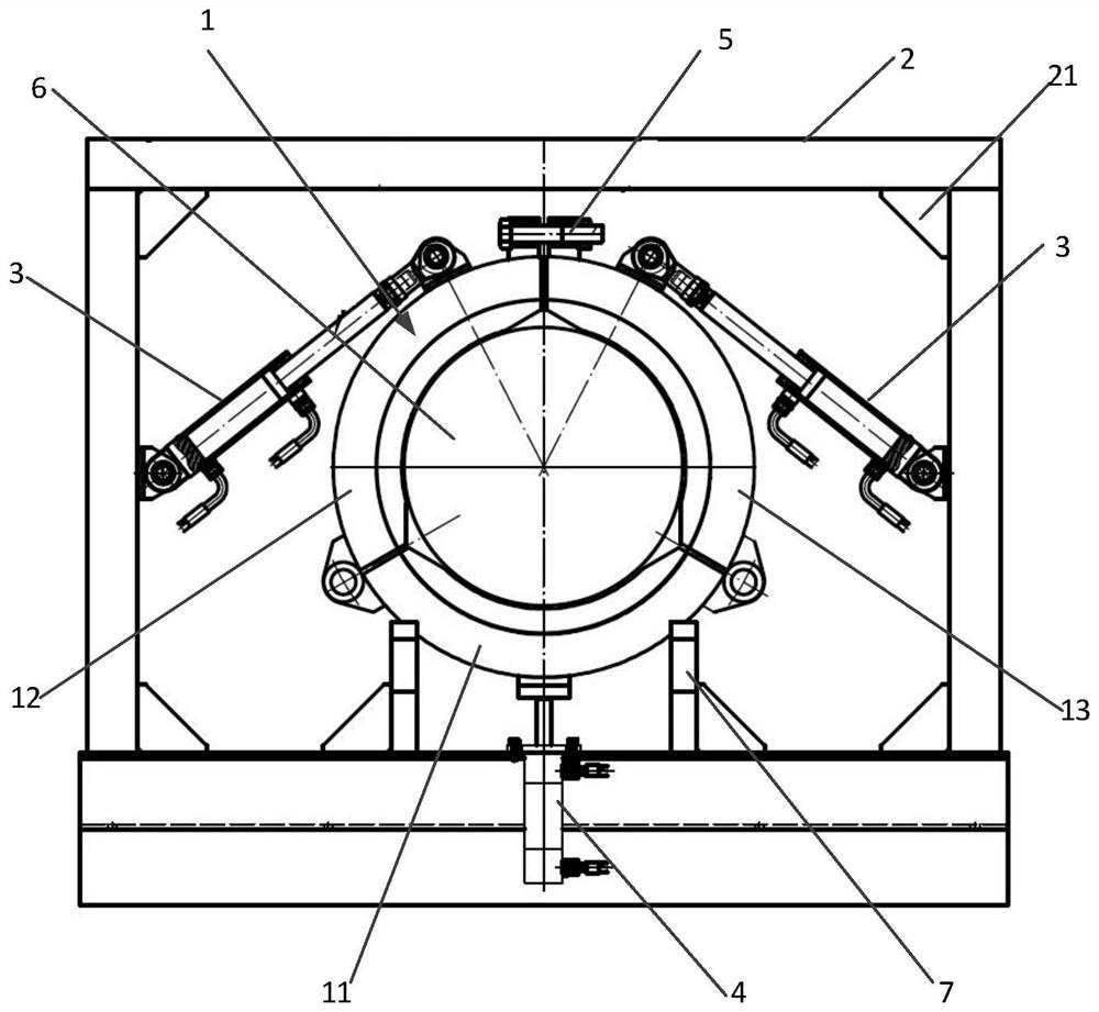
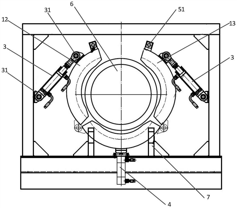
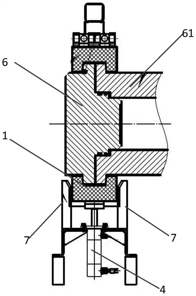
[0015] Such as figure 1 , 3 As shown, in one embodiment of the present invention, an automatic locking device for a three-piece clamp flange is disclosed, wherein the three-piece clamp flange 1 includes left hoops that are connected to each other to form a ring 12. The right hoop 13 and the bottom hoop 11, the left hoop 12 and the right hoop 13 are respectively axially connected to both ends of the bottom hoop 11 through one end, and the three are used to fix the pressure cylinder port 61 and the pressure cylinder end cover 6 together after being connected. .

[0016] The automatic locking device includes an outer frame reaction force frame 2, a clamping oil cylinder 3, a jacking oil cylinder 4 and a locking bolt 5.

[0017] The outer frame reaction frame 2 is a rectangular frame, which is set on the periphery ...


PUM


Abstract

The invention provides an automatic locking device for a three-piece type clamp flange. The three-piece type clamp flange comprises a left hoop, a right hoop and a bottom hoop; one end of the left hoop and one end of the right hoop are respectively connected with two end shafts of the bottom hoop; and the automatic locking device for the three-piece type clamp flange further comprises an outer frame reaction frame, clamping oil cylinders, a jacking oil cylinder and a locking nut, wherein the outer frame reaction frame is a rectangular frame and sleeves the periphery of the three-piece type clamp flange; the number of the clamping oil cylinders is two, the two ends of one clamping oil cylinder are connected with the outer frame reaction frame and the left hoop respectively, and the two endsof the other clamping oil cylinder are connected with the outer frame reaction frame and the right hoop respectively; two ends of the jacking oil cylinder are respectively connected with the outer frame reaction frame and the bottom hoop; and the locking nut is used for fixing the contact ends of the left hoop and the right hoop after the left hoop and the right hoop are folded. According to theautomatic locking device for the three-piece type clamp flange, on the basis that a traditional three-piece type clamp flange is opened, closed and locked completely through manual work, the outer frame reaction frame, the clamping oil cylinders and the jacking oil cylinder are additionally arranged, so that the whole full-automatic opening, closing and locking are achieved, the working efficiencyof opening, closing and locking is greatly improved, and labor force is liberated. And the safety protection degree can be improved by utilizing a locking bolt.

Description

technical field [0001] The invention relates to the field of nozzle sealing of pressure vessels, in particular to a device capable of quickly realizing automatic locking of a three-piece clamp flange through mechanical power. Background technique [0002] There are two ways to connect the end cover of a common pressure vessel (hereinafter referred to as the pressure cylinder) to the cylinder body, one is a bolt connection, and the other is a three-piece clamp flange connection. As the size and pressure level of the pressure cylinder continue to increase, the material cost and labor invested in the reliability and operability of the bolted connection are too large, and the opening and closing efficiency is extremely low, so it is gradually eliminated. [0003] The three-piece clamp flange is selected as the connection method between the end cover and the cylinder body of the large-size high-pressure pressure cylinder, which is more rapid, safe and operable. The three-piece c...

Claims


Application Information

Patent Timeline
Patent Type & Authority Applications(China)
IPC IPC(8): F16J13/10
CPCF16J13/10
Inventor 余杨许伟澎余建星韩梦雪徐盛博张春迎颜铠阳胡少谦刘泽生
Owner TIANJIN UNIV
Why Eureka
Try Eureka