
Pneumatic control valve device, pneumatic control valve group and pneumatic control assembly

A technology of pneumatic control valve and valve body, applied in the field of pneumatic control valve device and pneumatic control assembly, can solve the problems of low life, inconvenient maintenance, inconvenient use, etc.

Pending Publication Date: 2020-12-11
东莞市安海思精密电子有限公司
View PDF0 Cites 0 Cited by
  • Summary
  • Abstract
  • Description
  • Claims
  • Application Information

AI Technical Summary

Problems solved by technology

[0002] With the development of science and technology, people have higher and higher requirements for the comfort of car seats. Car seats usually have the functions of adjusting posture and shape, seat surface support, and seat surface massage. The combined pneumatic control of the pneumatic cavity (the pneumatic adjustment control device of the vehicle seat); but in the prior art, the pneumatic control mechanism of the complicated solenoid valve coil is usually used, which has the advantages of low life, inconvenient use, and inconvenient maintenance, etc. defect

Method used


Image

  • Pneumatic control valve device, pneumatic control valve group and pneumatic control assembly
  • Pneumatic control valve device, pneumatic control valve group and pneumatic control assembly
  • Pneumatic control valve device, pneumatic control valve group and pneumatic control assembly

Examples


Embodiment 1

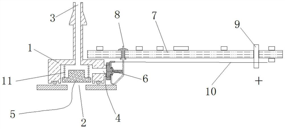
[0023] A pneumatic control valve device, comprising: a hollow valve body 1, an elastic component 6 and an electric control module;

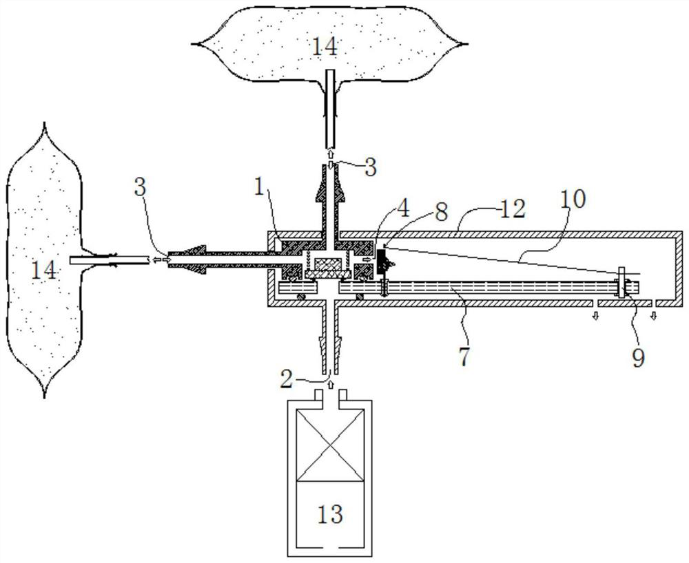
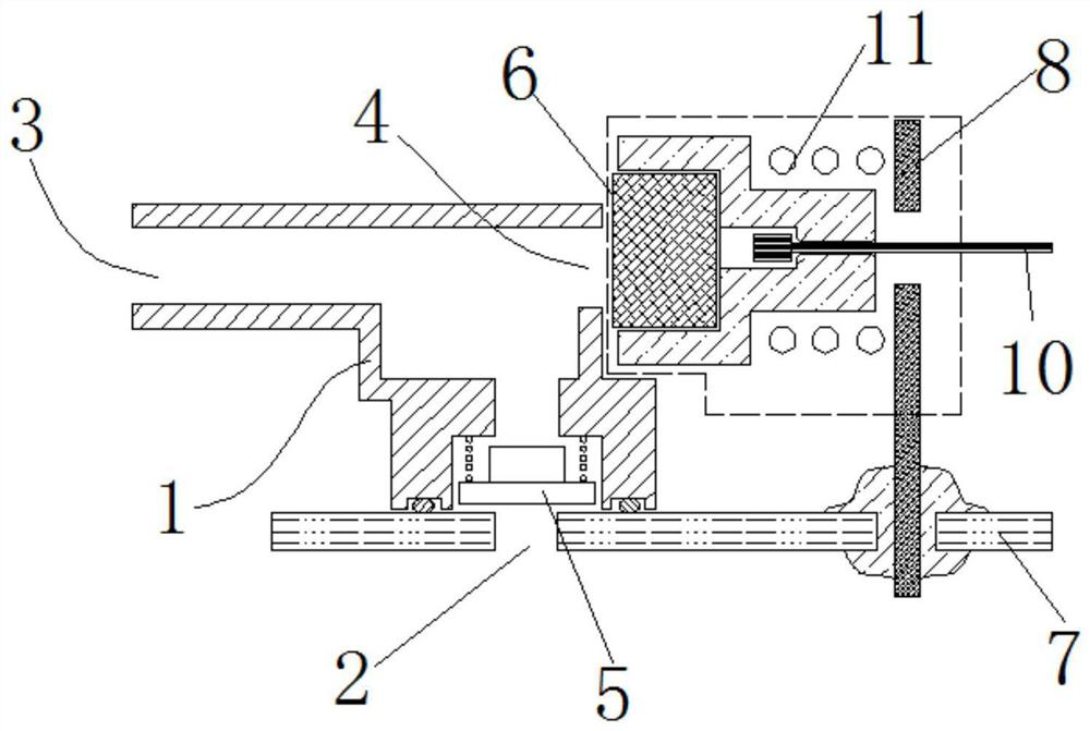
[0024] The valve body 1 is provided with an air intake passage 2, an inflation passage 3, and an exhaust passage 4 communicating with the outside, and a check valve 5 is provided in the air intake passage 2; the air intake passage 2 is used to introduce gas, The inflation passage 3 is used to supply air to the pneumatic cavity 14; the elastic component 6 is arranged on the end of the air leakage passage 4 communicating with the outside;

[0025] The electric control module includes: a circuit board 7, an elastic first electrode 8 and a memory alloy wire 10 connected to the first electrode 8; one end of the first electrode 8 is connected to the elastic component 6, and the first electrode The other end of 8 is electrically connected to the circuit board 7; the end of the memory alloy wire 10 away from the first electrode 8 is electrically connecte...

Embodiment 2

[0045] A pneumatic control valve group, including a pneumatic control valve device; the pneumatic control valve group includes: at least two of the pneumatic control valve devices; the circuit board 7 is electrically connected to the at least two pneumatic control valve devices respectively connect.

[0046] Such as Figure 5 As shown, two or more pneumatic control valve groups can be set to form a plurality of air circuit control linkage coordination mechanisms; wherein, the memory alloy wire can be bent and adjusted through the structural guide post 15 (one or more), and Adjustment of the wire length is thus obtained.

[0047] A pneumatic control assembly includes the aforementioned pneumatic control valve group; and also includes: an air pump 13 connected to the air intake passage 2 and a pneumatic chamber 14 connected to the inflation passage 3 . In this embodiment, a pneumatic control assembly may further include an auxiliary structure such as an air pipe connected to t...


PUM


Abstract

A pneumatic control valve device comprises an internal hollow valve body, an elastic assembly and an electric control module. The valve body is provided with an air inlet channel, an inflation channeland an air release channel which communicate with the outside, and a one-way valve is arranged in the air inlet channel. The air inlet channel is used for introducing air, and the inflation channel is used for supplying air to a pneumatic cavity. The elastic assembly is arranged at the end, communicating with the outside, of the air release channel. The electric control module comprises a circuitboard, an elastic first electrode and a memory alloy wire connected with the first electrode. One end of the first electrode is connected with the elastic assembly, and the other end of the first electrode is electrically connected with the circuit board. The end, far away from the first electrode, of the memory alloy wire is electrically connected with the circuit board. The electric control module is used for controlling the elastic assembly to close or open the air release channel.

Description

technical field [0001] The present disclosure generally relates to the technical field of automobile seats, and specifically relates to a pneumatic control valve device, a pneumatic control valve group and a pneumatic control assembly. Background technique [0002] With the development of science and technology, people have higher and higher requirements for the comfort of car seats. Car seats usually have the functions of adjusting posture and shape, seat surface support, and seat surface massage. The combined pneumatic control of the pneumatic cavity (the pneumatic adjustment control device of the vehicle seat); but in the prior art, the pneumatic control mechanism of the complicated solenoid valve coil is usually used, which has the advantages of low life, inconvenient use, and inconvenient maintenance, etc. defect. Contents of the invention [0003] In view of the above defects or deficiencies in the prior art, it is desired to provide a pneumatic control valve device...

Claims


Application Information

Patent Timeline
Patent Type & Authority Applications(China)
IPC IPC(8): F16K11/10F16K15/18F16K31/02F16K25/00F16K27/02B60N2/90A61H9/00
CPCB60N2/914B60N2/976F16K11/105F16K15/028F16K15/18F16K25/005F16K27/0263F16K31/025
Inventor 张海涛
Owner 东莞市安海思精密电子有限公司
Learn More