Anti-falling pipe joint

A technology for inner tubes and ends, which is applied in the field of pipe joints to prevent falling off, and can solve problems such as inconvenient and quick disconnection of butt joints and unsatisfactory sealing effects

Inactive Publication Date: 2020-12-11
XINJIANG BAYI IRON & STEEL
View PDF10 Cites 0 Cited by
  • Summary
  • Abstract
  • Description
  • Claims
  • Application Information

AI Technical Summary

Problems solved by technology

[0002] The pipe joints in the prior art mainly have the problems of inconvenient and quick disconnection and unsatisfactory sealing effect

Method used


Image

  • Anti-falling pipe joint

Examples


Embodiment Construction

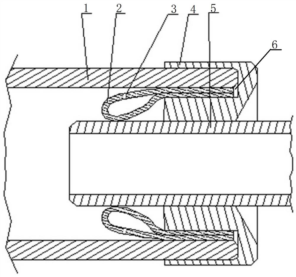
[0008] A pipe joint that prevents falling off, such as figure 1 As shown, it includes an outer tube 1 and an inner tube 5. The inner tube 5 is sleeved in a gland 4, and an annular groove 6 is arranged in the end surface of the gland 4 facing the end of the inner tube. A cylindrical cylindrical sealing bag 2 is set on the inner peripheral wall of the groove 6, and the inner surface of the outer end of the cylindrical cylindrical sealing bag 2 is attached to the outer peripheral wall of the end of the inner tube, and the end of the outer tube 1 is also fitted in the In the annular groove 6, the inner peripheral wall of the end of the outer tube 1 is in sealing contact with the outer peripheral surface of the cylindrical sealed bag 2, and is located at the inner side of the gland 4, the end of the inner tube 5 and the outer tube 1 Water inlet holes 3 are evenly spaced on the outer peripheral surface of the cylindrical sealed bag 2 between the inner peripheral walls. After the in...


PUM


Abstract

The invention discloses an anti-falling pipe joint. An outer pipe and an inner pipe are included, the inner pipe is sleeved with a gland, an annular groove is formed in the end face of the side, facing the inner pipe end, of the gland, and the inner circumferential wall of the annular groove is sleeved with a cylindrical sealing bag; and the inner surface of the outer side end of the cylindrical sealing bag is attached to the outer circumferential wall of the inner pipe end, the outer pipe end is also sleeved with the annular groove in a matched mode, and the inner circumferential wall of theouter pipe end makes contact with the outer circumferential face of the cylindrical sealing bag in a sealed mode. Water inlet holes are formed in the outer circumferential surface of the part, among the inner side end of the gland, the inner pipe end and the inner circumferential wall of the outer pipe, of the cylindrical sealing bag at equal intervals. The anti-falling pipe joint is good in sealing effect and extremely convenient to disassemble and assemble.

Description

technical field [0001] The invention relates to a pipe joint which prevents falling off. Background technique [0002] The pipe joints in the prior art mainly have the problems of inconvenient and quick disengagement of the butt joint and unsatisfactory sealing effect. Contents of the invention [0003] The object of the present invention is to provide a pipe joint that prevents falling off, which not only has a good sealing effect, but also is very convenient to disassemble and assemble. [0004] A pipe joint that prevents falling off to achieve the above purpose includes an outer pipe and an inner pipe, the inner pipe is set in a gland, and a circular groove is arranged in the end surface of the gland side facing the end of the inner pipe. A cylindrical cylindrical sealed bag is set on the inner peripheral wall of the annular groove, and the inner surface of the outer end of the cylindrical cylindrical sealed bag is attached to the outer peripheral wall of the end of th...

Claims


Application Information

Patent Timeline
Patent Type & Authority Applications(China)
IPC IPC(8): F16L17/10
CPCF16L17/10
Inventor 陈刚梁丽云赵军
Owner XINJIANG BAYI IRON & STEEL
Why Eureka
Try Eureka