Signal testing device of capacitive screen

A signal test and signal tester technology, used in measuring devices, parts of electrical measuring instruments, measuring electricity, etc., can solve problems such as knotting of test wires, and achieve the effect of avoiding automatic falling off and improving test efficiency.

Inactive Publication Date: 2022-05-13
江西视显高科技有限公司
View PDF1 Cites 0 Cited by
  • Summary
  • Abstract
  • Description
  • Claims
  • Application Information

AI Technical Summary

Problems solved by technology

[0004] In the process of testing the capacitive screen, the signal test device of the capacitive screen needs to insert the test pen into the detection position, and then the test line will move accordingly. Since the test lines are scattered, it is easy to have a test error during use. In order to solve the situation of knotted lines, a signal test device for capacitive screens that can be automatically wiped can be developed to guide the test lines separately to avoid knotting of the test lines.

Method used


Image

  • Signal testing device of capacitive screen
  • Signal testing device of capacitive screen
  • Signal testing device of capacitive screen

Examples


Embodiment 1

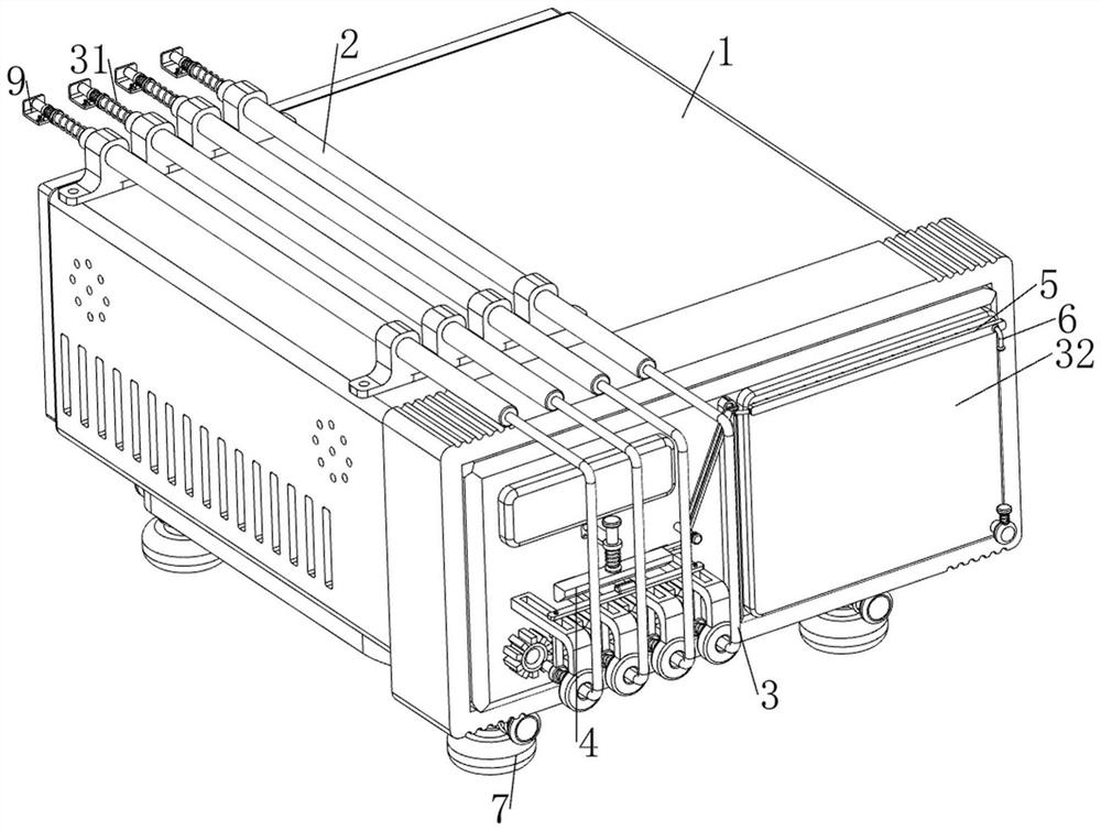
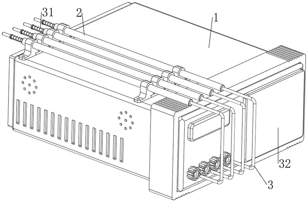
[0033] A signal testing device for a capacitive screen, such as Figure 1-3 As shown, it includes signal tester 1, guide rail 2, test line 3, first spring 31, display screen 32, wiring mechanism 4 and wiping mechanism 5. There are four guide rails 2 on the left side of the top of the instrument 1 through bolts. The test lines 3 are slidingly connected to the guide rails 2. The test lines 3 can slide back and forth in the guide rails 2. Both are provided with a first spring 31, under the action of the first spring 31, the test line 3 can be driven to move and reset, and the right front side of the signal tester 1 is provided with a display screen 32 through a bolt, and the display screen 32 is used to display the data of the signal test, A wiring mechanism 4 is provided between the left front side of the signal tester 1 and the test line 3 to facilitate the insertion of the test line 3 into the docking port of the signal tester 1, and a wiping mechanism 5 is provided on the rig...

Embodiment 2

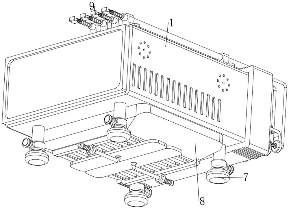
[0038] On the basis of Example 1, such as figure 1 and Figure 8 Shown, also comprise start-up mechanism 6, start-up mechanism 6 comprises fixed rod 61, master switch 62, the 5th spring 63 and pressure bar 64, display screen 32 lower right front side is provided with fixed rod 61, slides on fixed rod 61 There is a main switch 62 connected in the same way, and a fifth spring 63 is arranged between the lower part of the main switch 62 and the fixed rod 61. Under the action of the fifth spring 63, the main switch 62 can be driven to move and reset, and the right front side of the cleaning brush 51 is welded with a pressure The rod 64 and the cleaning brush 51 move up and down to drive the pressure rod 64 to move up and down, and the pressure rod 64 can press the main switch 62 .

[0039] The downward movement of the cleaning brush 51 drives the pressing rod 64 to move downward. When the pressing rod 64 is in contact with the main switch 62, the main switch 62 can be moved downwa...


PUM


Abstract

The invention relates to a signal testing device, in particular to a signal testing device of a capacitive screen. The technical problem is to provide a signal testing device for a capacitive screen, which can respectively guide testing wires, prevent the testing wires from being knotted and can realize automatic wiping at the same time. According to the technical scheme, the signal testing device of the capacitive screen comprises a signal tester, guide rails, testing lines, first springs and the like, the four guide rails are arranged on the left side of the top of the signal tester, the testing lines are arranged in the guide rails in a sliding mode, and the first springs are arranged between the rear sides of the testing lines and the rear sides of the guide rails. By moving the sliding plate, a test line can be quickly inserted into the docking port, then information testing is performed on the capacitive screen, tested data are transmitted into the display screen, people can conveniently watch the capacitive screen, the sliding plate can be clamped by the clamping block, and the test line is prevented from automatically falling off.

Description

technical field [0001] The invention relates to a signal testing device, in particular to a signal testing device for a capacitive screen. Background technique [0002] With the continuous development of technology, there are more and more capacitive screens. When producing capacitive screens, it is necessary to test the signal of the capacitive screen. Now there are many signal test devices on the market. [0003] The patent application number is CN201920555695.8, a capacitive screen signal test device, including a housing, a display screen, a power switch, a test line, a test pen, an external power cord, a detection circuit, a single-chip microcomputer, a signal converter, a partition, and a storage device and dust-proof device, the rear end of the display screen is bonded horizontally to the upper left side of the front end of the housing, the power switch is set on the lower left side of the front end of the housing, and the rear end of the test line is plugged into the ...

Claims


Application Information

Patent Timeline
Patent Type & Authority Applications(China)
IPC IPC(8): G01R31/00G01R1/02B08B1/00
CPCG01R31/00G01R1/02B08B1/006B08B1/002
Inventor 柳旭东
Owner 江西视显高科技有限公司
Why Eureka
Try Eureka