Optical imaging system, image pick-up module, electronic device and automobile
An optical imaging system and image-side technology, which is applied in the fields of electronic devices, automobiles, camera modules, and optical imaging systems, can solve the problems of high cost, difficult processing of the first lens, and easy ghosting of the first lens.
- Summary
- Abstract
- Description
- Claims
- Application Information
AI Technical Summary
Problems solved by technology
Method used
Image


Examples
no. 1 example
[0162] Please continue to see figure 1 , the optical imaging system 10 in this embodiment includes a first lens group, a second lens group, a stop STO and a third lens group in order from the object side to the image side.
[0163] The first lens group includes a first lens L1 with negative refractive power. The object side S1 of the first lens L1 is convex at the near optical axis, and the image side S2 of the first lens L1 is concave at the near optical axis.
[0164] The second lens group includes a second lens L2 with a positive refractive power and a third lens L3 with a positive refractive power in order from the object side to the image side. The object side S3 of the second lens L2 is a concave surface at the near optical axis. The image side S4 of the second lens L2 is convex at the near optical axis, the object side S5 of the third lens L3 is convex at the near optical axis, and the image side S6 of the third lens L3 is convex at the near optical axis.
[0165] The ...
no. 2 example
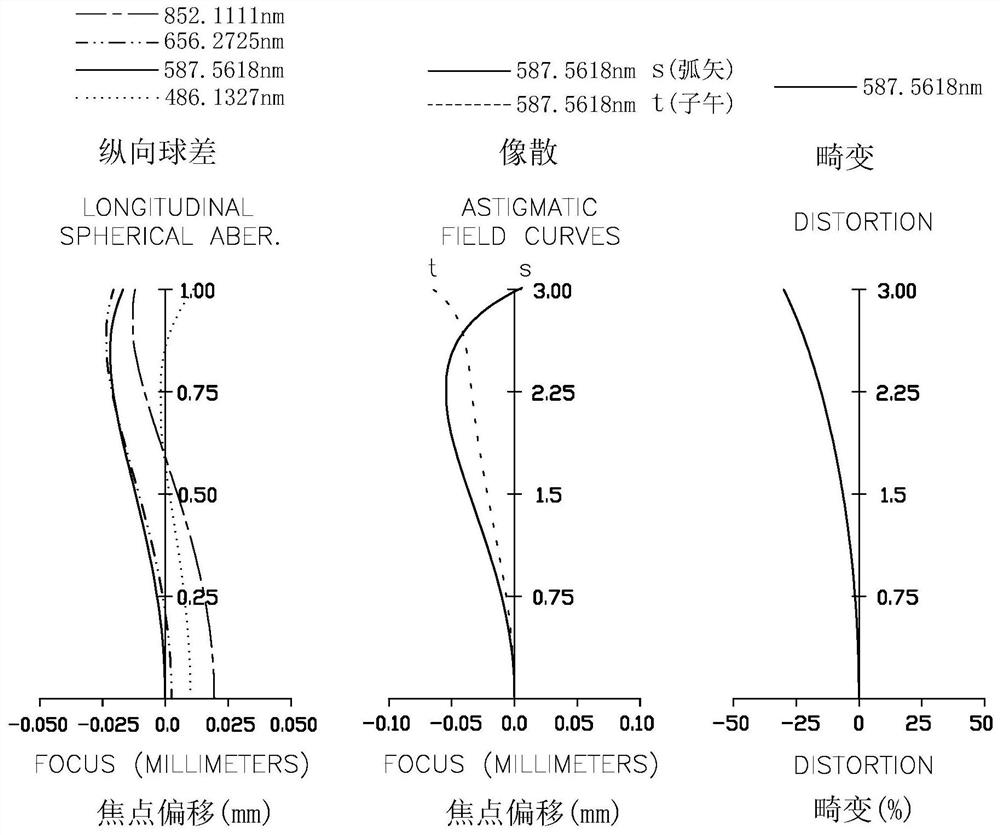
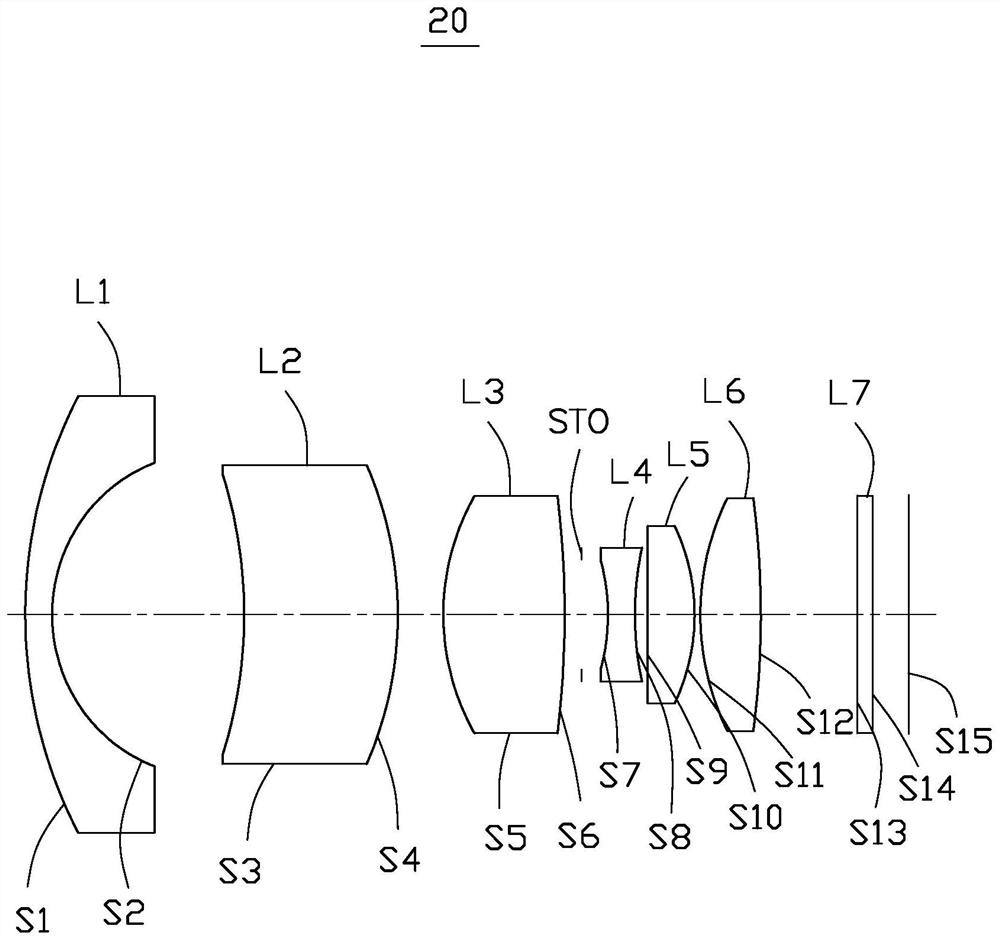
[0171] see image 3 , the optical imaging system 20 in this embodiment includes a first lens group, a second lens group, a stop STO and a third lens group in sequence from the object side to the image side.
[0172] The first lens group includes a first lens L1 with negative refractive power. The object side S1 of the first lens L1 is convex at the near optical axis, and the image side S2 of the first lens L1 is concave at the near optical axis.
[0173] The second lens group includes a second lens L2 with a positive refractive power and a third lens L3 with a positive refractive power in order from the object side to the image side. The object side S3 of the second lens L2 is a concave surface at the near optical axis. The image side S4 of the second lens L2 is convex at the near optical axis, the object side S5 of the third lens L3 is convex at the near optical axis, and the image side S6 of the third lens L3 is convex at the near optical axis.
[0174] The third lens group...
no. 3 example
[0180] see Figure 5 , the optical imaging system 30 in this embodiment includes a first lens group, a second lens group, a stop STO and a third lens group in order from the object side to the image side.
[0181] The first lens group includes a first lens L1 with negative refractive power. The object side S1 of the first lens L1 is concave at the near optical axis, and the image side S2 of the first lens L1 is concave at the near optical axis.
[0182] The second lens group includes a second lens L2 with a positive refractive power and a third lens L3 with a positive refractive power in order from the object side to the image side. The object side S3 of the second lens L2 is a convex surface at the near optical axis. The image side S4 of the second lens L2 is convex at the near optical axis, the object side S5 of the third lens L3 is convex at the near optical axis, and the image side S6 of the third lens L3 is convex at the near optical axis.
[0183] The third lens group i...
PUM
 Abstract
Description
Claims
Application Information
PatSnap Eureka turns technology decisions into work you can execute. Powered by our Innovation Knowledge Graph, it runs expert workflows across engineering, life sciences, materials and intellectual property. Get your review-ready output in minutes.


