
Vehicle structure with reinforced side rail

A technology for longitudinal beams and motor vehicles, applied in the directions of superstructure, substructure, vehicle components, etc., can solve problems such as unsatisfactory transmission, and achieve the effect of weakened force

Active Publication Date: 2020-12-11
PEZHO SITROEN AUTOMOBILS SA
View PDF9 Cites 0 Cited by
  • Summary
  • Abstract
  • Description
  • Claims
  • Application Information

AI Technical Summary

Problems solved by technology

As a result, rear impact stresses of average intensity acting on the rear wheels are not transmitted in a continuous manner across the side members and are therefore not ideally transmitted

Method used


Image

  • Vehicle structure with reinforced side rail

Examples


Embodiment Construction

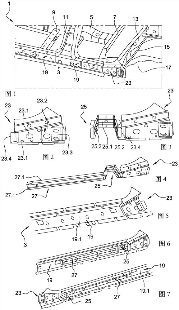
[0023] figure 1 is a partial perspective view of the underbody of a structure 1 of a motor vehicle showing side rails 3 and force transmission profiles according to the invention. In this case, the side member 3 is the side member on the left side of the vehicle, which is connected to the central duct 5 of the floor via the rear cross member 7 and the center cross member 9 and to the other parts of the structure 1 of the body via the center pillar 11 and the rear pillar 13 . Here, the rear pillars 13 together with the rear fenders 15 define wheel arch inner panels 17 of the rear wheels (not shown). The longitudinal members 3 of this underbody are generally formed by two profiles, wherein the outer profile 19 is arranged on the outside of the floor, and the inner profile is oriented on the side of the floor facing the outer profile 19 and thus in the figure 1 is not visible in . The two profiles each have a generally U-shaped section extending from the rear pillar 13 to the c...


PUM


Abstract

The invention relates to a motor vehicle structure comprising two side rails of the lower body frame, each formed by an inner profile and an outer profile. Said side rails also each comprise a force transmission profile (23), arranged in the region of the C-pillar and extending beyond the outer profile, which is designed to enter the U-shaped cross-section of the outer profile in the event of a rear impact from the rear wheel.

Description

technical field [0001] The invention relates to the deformation of a motor vehicle when the rear wheels are subjected to a collision. The present invention relates in particular to the body structure of a motor vehicle, and more particularly to an underbody rail located forward of the rear wheels. Background technique [0002] The body of a light motor vehicle generally comprises at the rear the rear doors, and uprights forming a substantially vertical hollow body, called rear pillars, which support the locks of these doors. The rear pillar is rigidly secured to a plurality of tubular elements of the body structure. In particular, the rear pillar is connected in the lower part to the lower body side rails and the floor cross member, and in the upper part to the rear cross member of the roof cover. The rear pillars are extended rearward by a sheet metal piece located inside the fenders called the fender liners and forming the wheel arches. The rear fender liner itself is r...

Claims


Application Information

Patent Timeline
IPC IPC(8): B62D21/15B62D25/02
CPCB62D21/15B62D25/025
Inventor 赛德·贝纳
Owner PEZHO SITROEN AUTOMOBILS SA
Learn More