Supercharge Your Innovation With Domain-Expert AI Agents!

Steel plate lifting feeding bending device

A technology of lifting feeding and bending devices, which is applied in the field of mechanical processing, can solve the problems affecting the use of steel plates, bending size changes, and bending position deviations, etc., to achieve safety and stability of the device, ensure stability, and ensure processing The effect of precision

Inactive Publication Date: 2020-12-18
高得民
View PDF0 Cites 0 Cited by
  • Summary
  • Abstract
  • Description
  • Claims
  • Application Information

AI Technical Summary

Problems solved by technology

[0003] Traditionally, when the steel plate is bent, due to the pressure, the steel plate is shifted in the process of pressing down, causing the bending position to shift, resulting in a change in the size of the bend, which affects the use of the steel plate. Therefore, it is necessary to The existing bending device is improved to solve the above problems

Method used


Image

  • Steel plate lifting feeding bending device
  • Steel plate lifting feeding bending device
  • Steel plate lifting feeding bending device

Examples


Embodiment 1

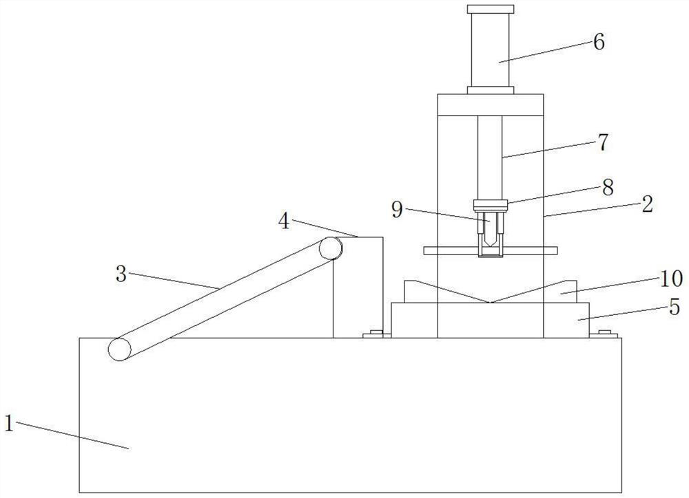
[0021] Please refer to the figure, in the embodiment of the present invention, a bending device for lifting and feeding steel plates includes a base 1, a bracket 2, a hydraulic cylinder 6, a lifting column 7, a lifting seat 8, a bending pressure head 9 and a bending model 10 The support 2 is fixedly installed on the base 1, the support 2 is a gantry structure, and the upper surface of the corresponding base 1 in the support 2 is fixedly installed with a mounting seat 5, and the mounting seat 5 is fixed on the base 1 by bolts, which is convenient for the mounting seat 5 Disassembly, a bending model 10 is fixed on the mounting base 5, and the steel plate is bent on the bending model 10; a vertical hydraulic cylinder 6 is fixedly arranged on the top of the support 2, and the output shaft of the hydraulic cylinder 6 is vertical Downward, the lower end of the output shaft of the hydraulic cylinder 6 is coaxially fixedly connected with a lifting column 7, and the lifting column 7 is ...

Embodiment 2

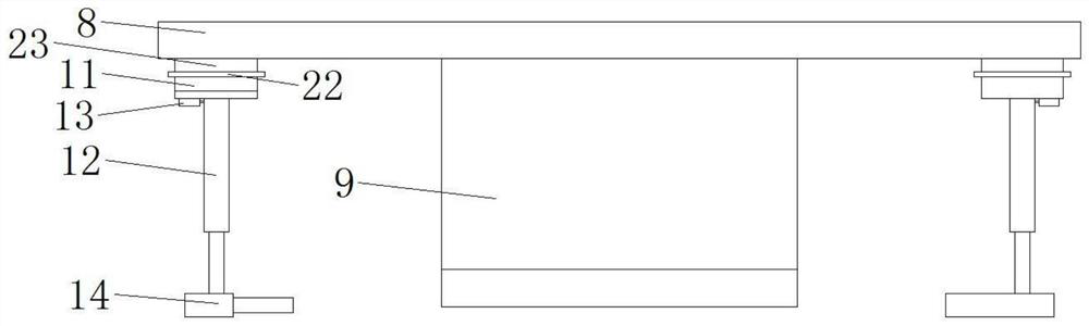
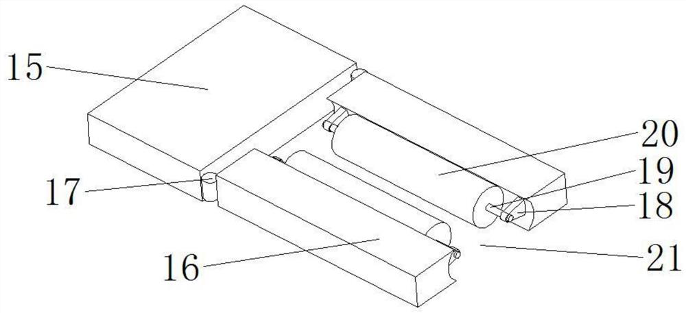
[0025] On the basis of Embodiment 1, a sliding connection can be used between the mounting block 11 and the lifting seat 8, specifically, a sliding seat 23 is provided between the mounting block 11 and the lifting seat 8, and the sliding seat 23 is slidably connected to the lifting seat 8. The lower surface of the seat 8 makes the sliding seat 23 move in the horizontal direction, adjusts the distance with the bending head 9, and adjusts the distance through the steel plate support structures 14 at both ends, so as to adapt to the bending of steel plates of different lengths; the sliding seat 23 It is rotationally connected with the mounting block 11 through a horizontal rotating shaft 22, and the rotating shaft 22 is parallel to the support shaft 19, so that the mounting block 11 swings back and forth around the rotating shaft 22, so that the horizontally pushed steel plate enters between the two steel plate support structures 14 Installation between the steel plate support str...


PUM


Abstract

The invention relates to the field of machining, and particularly discloses a steel plate lifting feeding bending device. The device comprises a base, a support, a hydraulic cylinder, a lifting column, a lifting base, a bending pressing head and a bending model, wherein mounting blocks are arranged at the front end and the rear end of the bending pressing head correspondingly, vertical air cylinders are fixedly mounted on the lower sides of the mounting blocks, steel plate supporting structures are fixedly mounted at the lower ends of the air cylinders, the steel plate supporting structures comprise fixing plates fixedly connected with the lower ends of the air cylinders, two corresponding parallel contact plates are arranged at the end, facing the bending pressing head, of each fixing plate, and corresponding guide rollers horizontally parallel to the corresponding contact plates are installed on the sides, corresponding to each other, of the two corresponding contact plates of each fixing plate. According to the device, a steel plate is fixedly pressed at the lower end of the bending pressing head, so that the steel plate cannot deviate in the bending process, the bending stability is guaranteed, and the machining precision is guaranteed; and in the steel plate bending process, the guide rollers always make contact with the steel plate, so that the steel plate is tightly attached to the bending pressing head and cannot be separated.

Description

technical field [0001] The invention relates to the field of mechanical processing, in particular to a bending device for lifting and feeding steel plates. Background technique [0002] Steel plates are frequently used steel structures, and there are more and more plates that need to be bent, and the thickness of the bent plates is getting thicker and thicker. The traditional steel plate bending uses a hydraulic press to form the plate. The steel plate to be bent is placed on the working platform of the hydraulic machine, and then the hydraulic machine bends the steel plate through the pressure generated by the hydraulic transmission system. [0003] Traditionally, when the steel plate is bent, due to the pressure, the steel plate is shifted in the process of pressing down, causing the bending position to shift, resulting in a change in the size of the bend, which affects the use of the steel plate. Therefore, it is necessary to The existing bending device is improved to so...

Claims


Application Information

Patent Timeline
Patent Type & Authority Applications(China)
IPC IPC(8): B21D5/01B21D43/00B21D43/12B21D43/13
CPCB21D5/002B21D5/01B21D43/026B21D43/12B21D43/13
Inventor 高得民
Owner 高得民
Features
  • R&D
  • Intellectual Property
  • Life Sciences
  • Materials
  • Tech Scout
  • Unparalleled Data Quality
  • Higher Quality Content
  • 60% Fewer Hallucinations
Learn More