Photoelectric device aging test fixture

A technology for optoelectronic devices and test fixtures, which can be used in optical instrument testing, machine/structural component testing, electrical measuring instrument components, etc. , to achieve the effect of solving a narrower scope of application

Inactive Publication Date: 2020-12-18
HANGZHOU KUANFU TECH
View PDF1 Cites 2 Cited by
  • Summary
  • Abstract
  • Description
  • Claims
  • Application Information

AI Technical Summary

Problems solved by technology

[0006] The object of the present invention is to provide a photoelectric device burn-in test fixture to solve the problems of inconvenient placement of photoelectric devices, limited number of single measurements and narrow application range in the existing photoelectric device test fixture proposed in the background art

Method used


Image

  • Photoelectric device aging test fixture
  • Photoelectric device aging test fixture
  • Photoelectric device aging test fixture

Examples


Embodiment Construction

[0026] The following will clearly and completely describe the technical solutions in the embodiments of the present invention with reference to the accompanying drawings in the embodiments of the present invention. Obviously, the described embodiments are only some, not all, embodiments of the present invention.

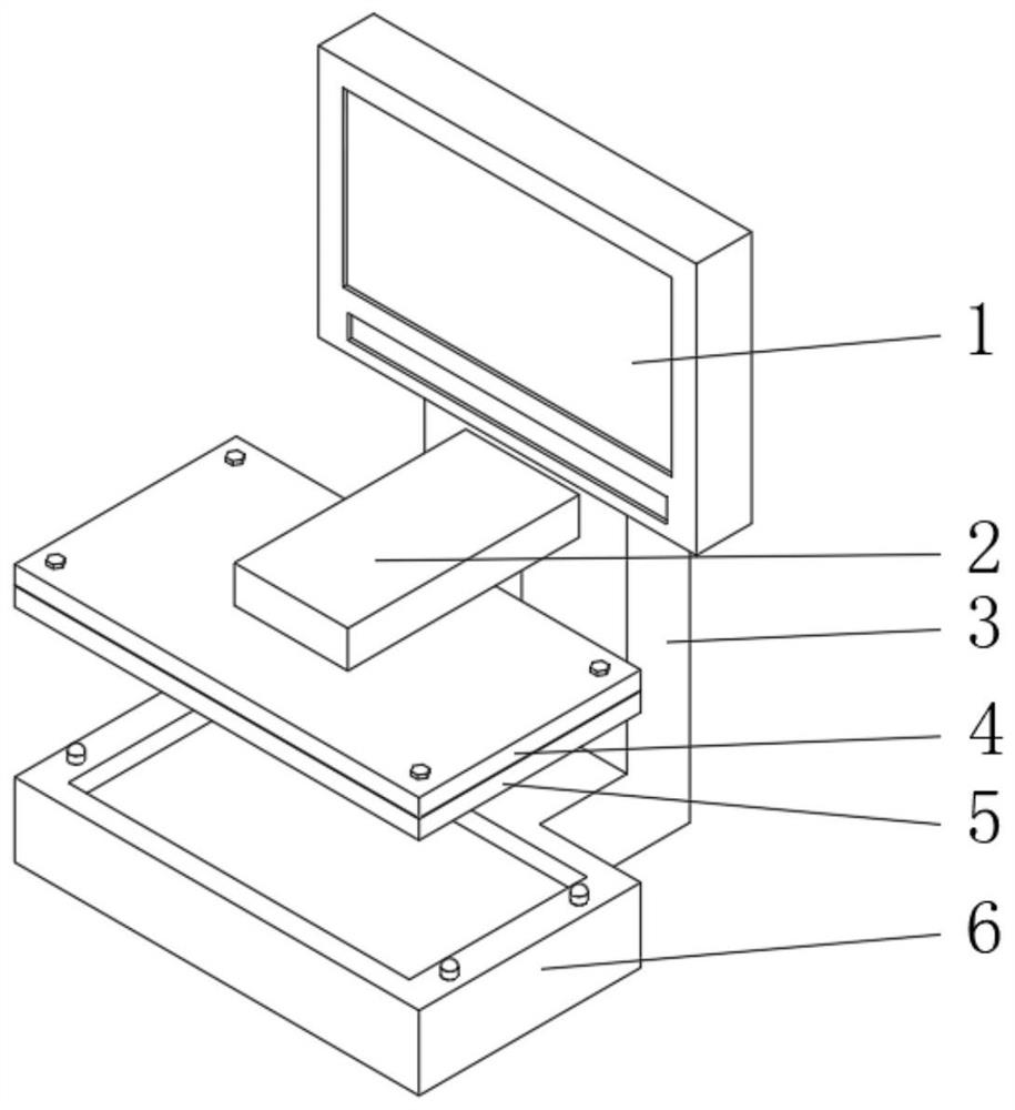
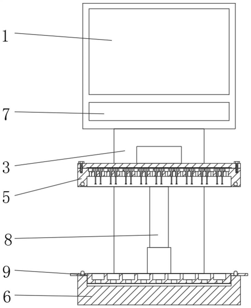
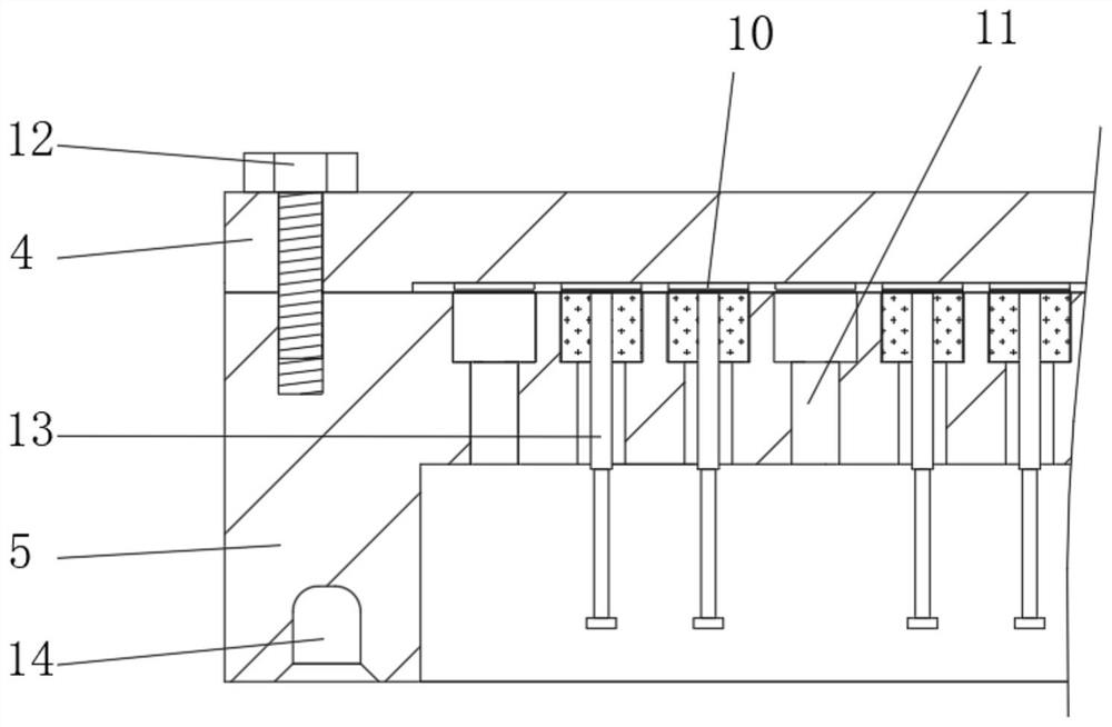
[0027] see Figure 1-5 As shown, a photoelectric device burn-in test fixture includes a base 6, one side of the base 6 is fixedly connected with a support column 3 and a cylinder 8, the top of the support column 3 is fixedly connected with a display screen 1, and the bottom end of the display screen 1 is provided with There is a control panel 7, a beam 2 is fixedly connected to the top of the cylinder 8, a first fixed plate 4 is fixedly connected to the bottom of the side of the beam 2 away from the cylinder 8, and a second fixed plate 5 is fixedly connected to the bottom of the first fixed plate 4 , the first fixed plate 4 and the second fixed plate 5 are fixedly co...


PUM


Abstract

The invention discloses a photoelectric device aging test fixture, which relates to the technical field of photoelectric device testing, and comprises a base, one side of the base is fixedly connectedwith a support column and an air cylinder, the top end of the support column is fixedly connected with a display screen, the bottom end of the display screen is provided with a control panel, and thetop end of the air cylinder is fixedly connected with a cross beam. A first fixing plate is fixedly connected to the bottom end of the side, away from the air cylinder, of the cross beam, a second fixing plate is fixedly connected to the bottom end of the first fixing plate, a first copper sheet is fixedly connected to the bottom end of the first fixing plate, a limiting through hole is formed inthe second fixing plate, and a connecting device is arranged in the limiting through hole; the connecting device is composed of an insulating block, a fixed cylinder, a spring and a movable rod. Thephotoelectric device aging test fixture solves the problems that photoelectric devices of an existing photoelectric device test fixture are inconvenient to place, the number of the photoelectric devices measured at a time is limited, and the application range is narrow.

Description

technical field [0001] The invention relates to the technical field of photoelectric device testing, in particular to a photoelectric device aging test jig. Background technique [0002] Optoelectronic devices refer to devices made according to the photoelectric effect called optoelectronic devices, also known as photosensitive devices. There are many types of photoelectric devices, but their working principles are all based on the physical basis of the photoelectric effect. At present, in order to ensure the normal use of optoelectronic devices, it is usually necessary to use testing equipment to test the optoelectronic devices. [0003] In the Chinese utility model patent application number: CN201820483310.7, there is disclosed a photoelectric device test fixture, the photoelectric device test fixture includes a base, a test part, a support part and a clamping part, the bottom of the test part is fixed with a base, so The rear side of the test part is fixedly provided wi...

Claims


Application Information

Patent Timeline
Patent Type & Authority Applications(China)
IPC IPC(8): G01R1/04G01M11/00
CPCG01M11/00G01R1/0408
Inventor 唐林浩
Owner HANGZHOU KUANFU TECH
Why Eureka
Try Eureka