Intelligent control insecticidal lamp
An intelligent control and insecticidal lamp technology, which can be used in devices for capturing or killing insects, animal husbandry, lighting and heating equipment, etc. It can solve the problems of acute animal poisoning, insignificant insecticidal effect, and low safety.
- Summary
- Abstract
- Description
- Claims
- Application Information
AI Technical Summary
Problems solved by technology
Method used
Image
Examples
Embodiment 1
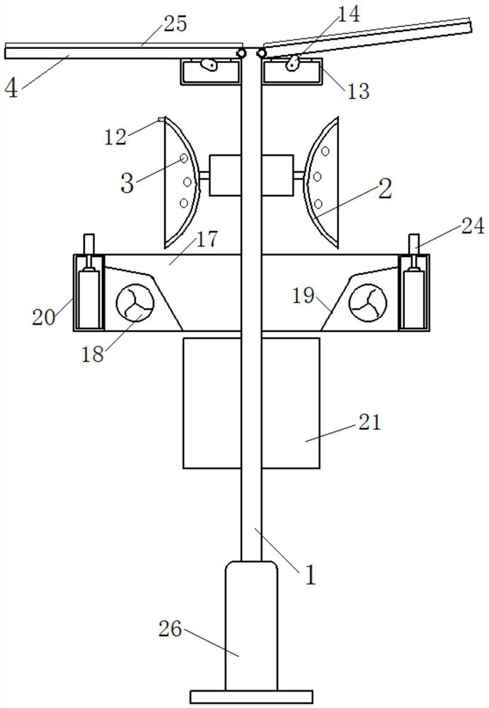
[0056] Such as Figure 1 to Figure 5 As shown, an intelligent control insecticidal lamp includes: a support frame 1 fixed on the ground; two arc-shaped lampshades 2 located above the support frame 1, and two arc-shaped lampshades 2 wrap around the support frame The central axis of 1 is evenly distributed around the circumference; the light source 3 is arranged on the inner side of the arc lampshade 2; two reflectors 4 are hinged on the upper end of the support frame 1 and are located on the left and right sides of the support frame 1; The first rotating mechanism, the fixed end of each first rotating mechanism is all fixed on the support frame 1, the output end of each first rotating mechanism is respectively hinged with the outer side of a described arc lampshade 2, the first rotating mechanism It is used to drive the arc lampshade 2 to rotate to change the irradiation angle of the light source 3, and then change the reflection distance of the reflector 4; two push mechanisms...
Embodiment 2
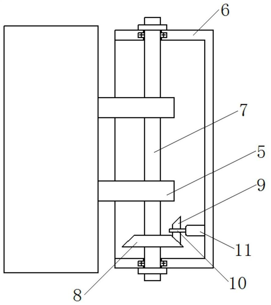
[0059] This embodiment is based on Embodiment 1. The first rotating mechanism includes: two connecting rods 5, one end of the two connecting rods 5 is fixedly connected to the arc lampshade 2, and the other ends of the two connecting rods 5 are provided with Through hole; the first housing 6 is sleeved on the outside of the two connecting rods 5, and the first housing 6 is fixedly connected with the support frame 1; the first rotating shaft 7, the first rotating shaft 7 is from top to bottom Pass through the through holes provided on the first housing 6 and the two connecting rods 5 in turn, and be fixedly connected with the connecting rods 5, while the upper and lower ends of the first rotating shaft 7 are also connected to the first rotating shaft 7 through a bearing. The first housing 6 is connected; the driven bevel gear 8 is sleeved and fixed on the outside of the first rotating shaft 7; the driving bevel gear 9 is meshed with the driven bevel gear 8; the second rotating s...
Embodiment 3
[0062] This embodiment is based on Embodiment 1, and the pushing mechanism includes: a second housing 13, fixed on the support frame 1; an eccentric cam 14, located inside the second housing 13, and the edge of the eccentric cam 14 is aligned with the The reflector 4 contacts; the third rotating shaft 15 runs through the eccentric cam 14; the second motor 16, whose output shaft is connected with the third rotating shaft 15, and the second motor 16 is used to drive the eccentric cam 14 to rotate, The rotation of the eccentric cam 14 pushes the reflector 4 to rotate around the upper end of the support frame 1, and the shortest distance between the edge of the eccentric cam 14 and the central axis of the third rotating shaft 15 is equal to the distance between the central axis of the third rotating shaft 15 and the upper end of the second housing 13 distance.
[0063] The intelligent control insecticidal lamp provided by the present invention is provided with a push mechanism, an...
PUM
 Abstract
Description
Claims
Application Information
 - R&D
- Intellectual Property
- Life Sciences
- Materials
- Tech Scout
- Unparalleled Data Quality
- Higher Quality Content
- 60% Fewer Hallucinations
Browse by: Latest US Patents, China's latest patents, Technical Efficacy Thesaurus, Application Domain, Technology Topic, Popular Technical Reports.
© 2025 PatSnap. All rights reserved.Legal|Privacy policy|Modern Slavery Act Transparency Statement|Sitemap|About US| Contact US: help@patsnap.com


