
Rapid locking device and control cabinet

A technology of locking device and power control cabinet, which is applied to substation/distribution device housing, substation/switchgear cooling/ventilation, substation/switch arrangement details, etc., can solve maintenance difficulties, disadvantageous power cabinet maintenance, and time-consuming disassembly labor and other problems, to achieve the effect of strengthening structural sealing, improving equipment safety and service life, and improving safety

Inactive Publication Date: 2020-12-25
北京国电光宇机电设备有限公司
View PDF9 Cites 0 Cited by
  • Summary
  • Abstract
  • Description
  • Claims
  • Application Information

AI Technical Summary

Problems solved by technology

If the electrical components inside the power cabinet are damaged, when maintaining the electrical components inside the power cabinet, it is generally necessary to open the door for maintenance, but due to the design characteristics of the cabinet, it is generally very difficult to maintain, unless Disassemble the entire cabinet, but this kind of disassembly is time-consuming and laborious, which is not conducive to the maintenance of the power cabinet

Method used


Image

  • Rapid locking device and control cabinet
  • Rapid locking device and control cabinet
  • Rapid locking device and control cabinet

Examples


Embodiment Construction

[0046] Reference will now be made in detail to the exemplary embodiments, examples of which are illustrated in the accompanying drawings. When the following description refers to the accompanying drawings, the same numerals in different drawings refer to the same or similar elements unless otherwise indicated. The implementations described in the following exemplary examples do not represent all implementations consistent with the present invention. Rather, they are merely examples of apparatuses and methods consistent with aspects of the invention as recited in the appended claims.

[0047]The terminology used in the present invention is for the purpose of describing particular embodiments only and is not intended to limit the invention. As used herein and in the appended claims, the singular forms "a", "the", and "the" are intended to include the plural forms as well, unless the context clearly dictates otherwise. It should also be understood that the term "and / or" as used...


PUM


Abstract

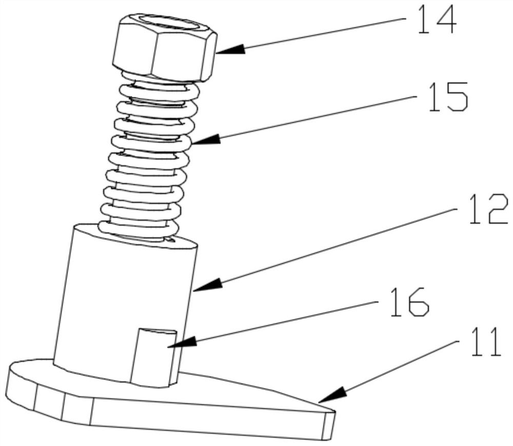
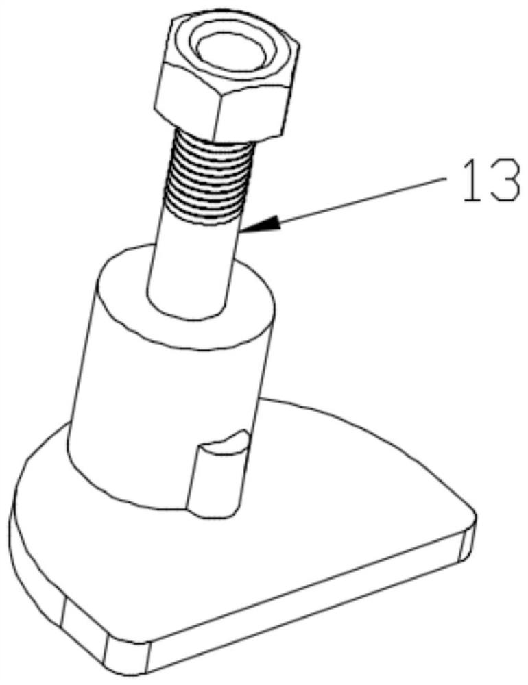
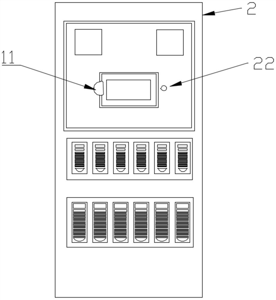
The invention relates to the technical field of power device cabinet assembly, in particular to a rapid locking device and a control cabinet. The device comprises a base, a first supporting body, thelower end of which is connected with the upper face of the base, and a second supporting body, the lower end of which is connected with the upper end of the first supporting body, wherein a blocking body is arranged on the side face of the first supporting body, a thread is arranged on the outer side face of the second supporting body, and the thread is sleeved with a nut. A spring is arranged between the lower side of the nut and the upper end of the first supporting body, the outer side face of the second supporting body is further sleeved with the spring, and the nut can move along the threads and extrude or release the spring to deform. The rapid locking device solves the technical problem that electrical elements cannot be quickly installed due to the arrangement of the rapid lockingdevice and the power control cabinet, and the technical effect of improving the installation efficiency is achieved.

Description

Technical field: [0001] The invention relates to the technical field of electric device cabinet assembly, in particular to a quick locking device and a control cabinet. Background technique: [0002] The power cabinet is a device used to install electrical components inside. It is usually installed outdoors away from the power supply center. The installed electrical components include circuit breakers, conventional relays, metering instruments, etc. The above electrical components are usually installed on the side of the cabinet through fixtures The inner side of the board or rear board. If the electrical components inside the power cabinet are damaged, when maintaining the electrical components inside the power cabinet, it is generally necessary to open the door for maintenance, but due to the design characteristics of the cabinet, it is generally very difficult to maintain, unless The entire cabinet is disassembled, but this disassembly is time-consuming and laborious, wh...

Claims


Application Information

Patent Timeline
IPC IPC(8): H02B1/32H02B1/044H02B1/56H02B1/28H02B1/54
CPCH02B1/32H02B1/044H02B1/565H02B1/28H02B1/54
Inventor 魏合宇肖功科李伟杰邓宇
Owner 北京国电光宇机电设备有限公司
Learn More