Supercharge Your Innovation With Domain-Expert AI Agents!

Modulation and overmodulation method and device for SVPWM control

A technology of modulation and modulation ratio, which is applied in the control system, AC motor control, electrical components, etc., can solve the problems of complex SVPWM modulation process, complex calculation, and large amount of calculation, and achieve the effect of simplifying the modulation and over-modulation process

Inactive Publication Date: 2020-12-25
BEIJING CHJ AUTOMOTIVE TECH CO LTD
View PDF4 Cites 0 Cited by
  • Summary
  • Abstract
  • Description
  • Claims
  • Application Information

AI Technical Summary

Benefits of technology

The technology described for controlling an electric motor's power involves adjustment or over-driving certain parameters during operation. This helps improve efficiency and performance. By calculating these values correctly, it becomes easier than ever before to calculate specifications with more detail.

Problems solved by technology

This patented describes different ways for controlling an electric device's operation through adjustment or pulsing signals. One way involves calculating specific areas within certain coordinates before sending them out with pulses. Another approach uses classical techniques like phase-shifted dither technology but also includes various factors involved during calculations involving complex evaluation processes between these technical problem addressed in previous researchers.

Method used


Image

  • Modulation and overmodulation method and device for SVPWM control
  • Modulation and overmodulation method and device for SVPWM control
  • Modulation and overmodulation method and device for SVPWM control

Examples


Embodiment Construction

[0021] Exemplary embodiments of the present disclosure will be described in more detail below with reference to the accompanying drawings. Although exemplary embodiments of the present disclosure are shown in the drawings, it should be understood that the present disclosure may be embodied in various forms and should not be limited by the embodiments set forth herein. Rather, these embodiments are provided for more thorough understanding of the present disclosure and to fully convey the scope of the present disclosure to those skilled in the art.

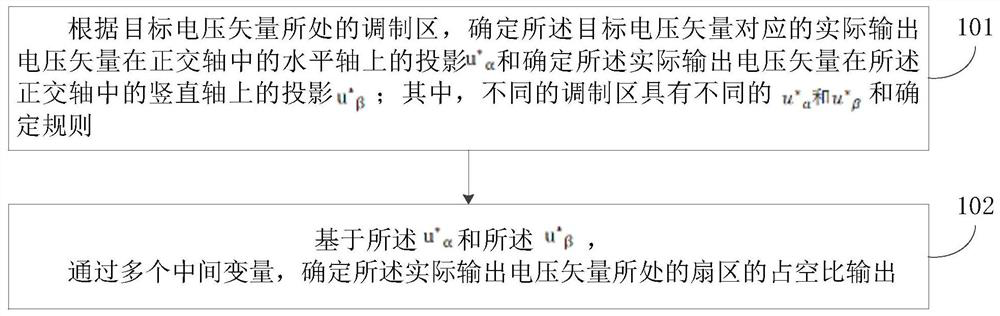
[0022] In the first aspect, embodiments of the present disclosure provide a modulation method controlled by SVPWM, such as figure 1 As shown, the method mainly includes:

[0023] 101. According to the modulation area where the target voltage vector is located, determine the projection u of the actual output voltage vector corresponding to the target voltage vector on the horizontal axis in the orthogonal axis * α and determine th...


PUM


Abstract

The embodiment of the invention discloses a modulation and overmodulation method and device for SVPWM control, relates to the technical field of motor control, and mainly aims to simplify the implementation process of modulation and overmodulation in SVPWM control. The method comprises the steps of determining a projection u*[alpha] of an actual output voltage vector corresponding to a target voltage vector on a horizontal axis in a quadrature axis and determining a projection u*[beta] of the actual output voltage vector on a vertical axis in the quadrature axis according to a modulation region where the target voltage vector is located, wherein different modulation regions have different u*[alpha] and u*[beta] determination rules; and based on the u*[alpha] and the u*[beta], determining duty ratio output of a sector where the actual output voltage vector is located through a plurality of intermediate variables.

Description


Claims


Application Information

Patent Timeline
Owner BEIJING CHJ AUTOMOTIVE TECH CO LTD
Features
  • R&D
  • Intellectual Property
  • Life Sciences
  • Materials
  • Tech Scout
  • Unparalleled Data Quality
  • Higher Quality Content
  • 60% Fewer Hallucinations
Learn More