
Raman laser modulation device and method

A Raman laser and modulation method technology, applied in the field of precision instruments, can solve the problems of complex preparation process, inability to switch Raman laser switches, etc., and achieve the effect of simplifying the modulation process

Active Publication Date: 2022-05-06
TSINGHUA UNIV
View PDF4 Cites 0 Cited by
  • Summary
  • Abstract
  • Description
  • Claims
  • Application Information

AI Technical Summary

Problems solved by technology

[0004] Based on this, in order to solve the problem that the preparation process required by the optical microcavity to generate Raman laser is very complicated and the Raman laser switch cannot be switched in the traditional technology, the present invention proposes a Raman laser modulation device and method

Method used


Image

  • Raman laser modulation device and method
  • Raman laser modulation device and method
  • Raman laser modulation device and method

Examples


Embodiment Construction

[0037] In order to make the above-mentioned purpose, features and advantages of the present application more obvious and understandable, the specific implementation manners of the present application will be described in detail below in conjunction with the accompanying drawings. In the following description, numerous specific details are set forth in order to provide a thorough understanding of the application. However, the present application can be implemented in many other ways different from those described here, and those skilled in the art can make similar improvements without departing from the connotation of the present application. Therefore, the present application is not limited by the specific implementation disclosed below.

[0038] The serial numbers numbered for components in this document, such as "first", "second", etc., are only used to classify the described objects and do not have any sequence or technical meaning. The "connection" and "connection" mention...


PUM

PropertyMeasurementUnit
diameteraaaaaaaaaa
diameteraaaaaaaaaa
diameteraaaaaaaaaa

Abstract

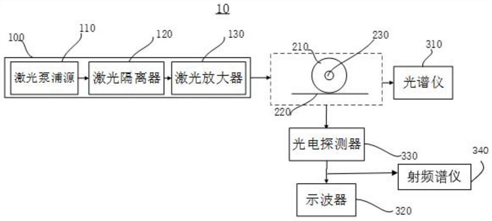
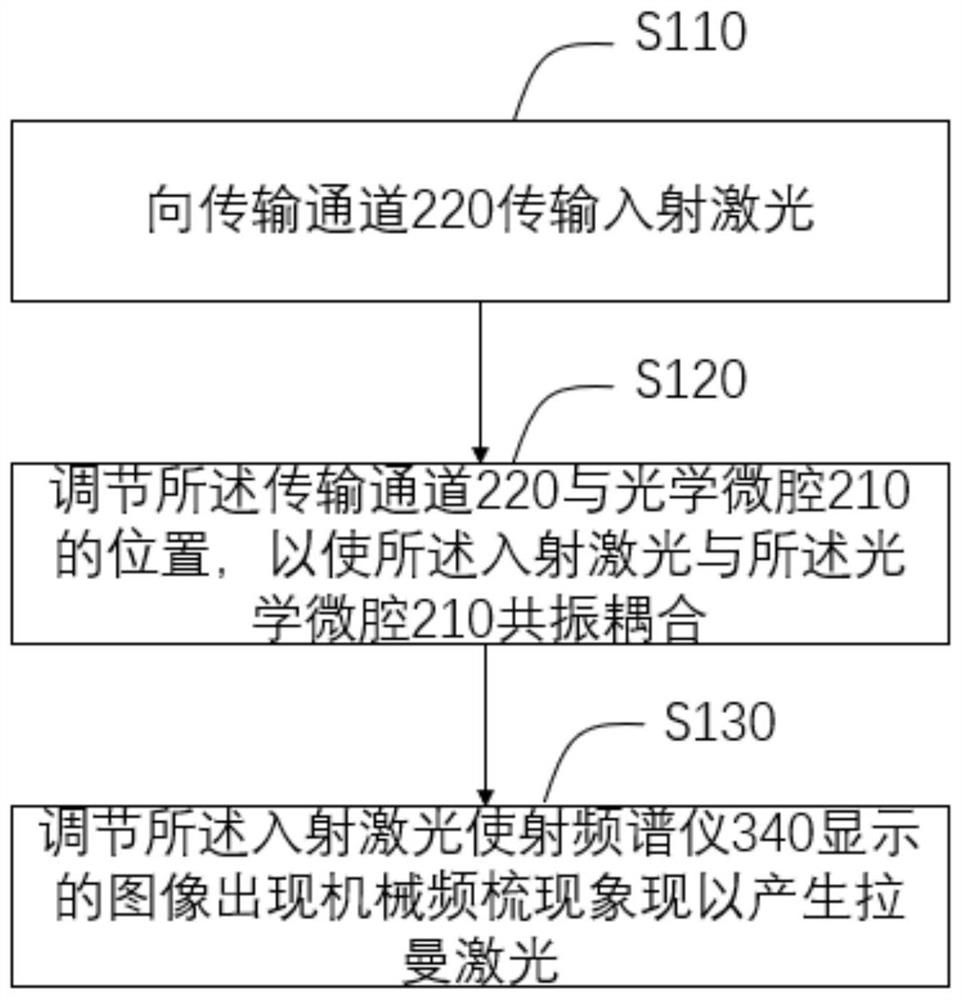
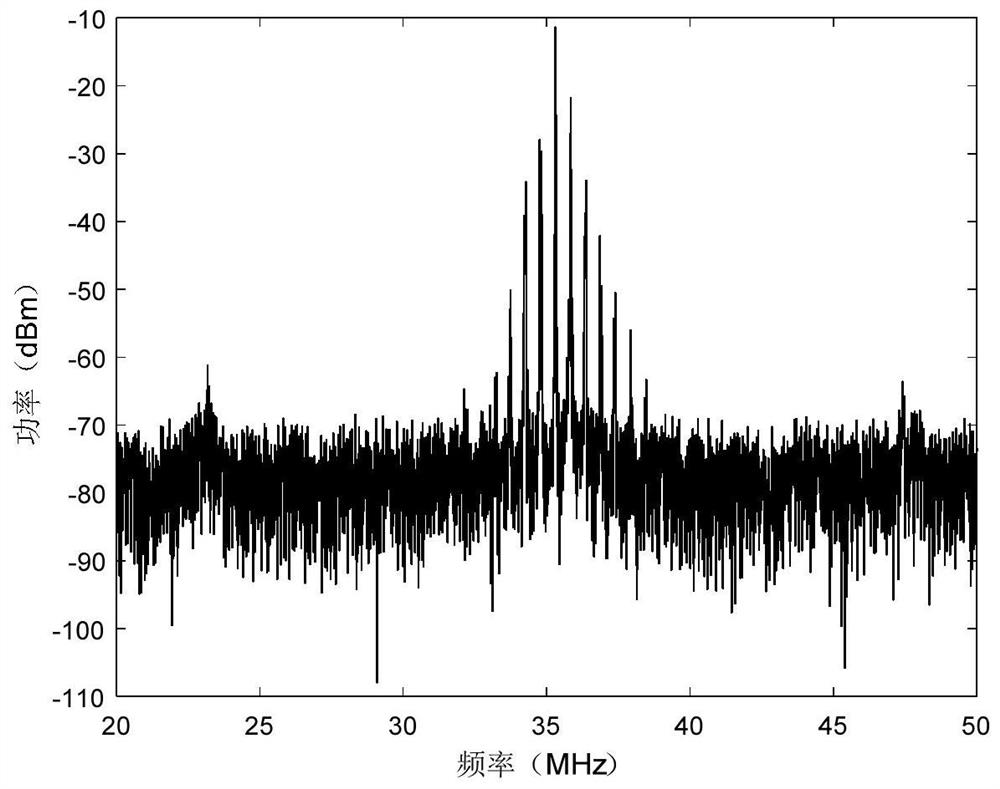
The Raman laser modulation device and method provided in the embodiments of the present application first emits laser light to the laser transmission channel, and then adjusts the positional relationship between the laser transmission channel and the optical microcavity, so that the laser passes through the laser transmission channel and the The optical microcavity resonant coupling described above. Then, the laser is further adjusted to make a mechanical frequency comb phenomenon appear in the image displayed by the radio frequency spectrometer to generate Raman laser. The Raman laser modulation method and device described in the present application effectively switch the Raman laser by introducing the mechanical frequency comb characteristic, and realize the function of an optical switch. This application simplifies the preparation process and provides a new idea for the application of Raman laser generation and optical switch.

Description

technical field [0001] The present application relates to the field of precision instruments, in particular to a Raman laser modulation device and method. Background technique [0002] Whispering gallery mode optical microcavities have extremely high quality factor and small mode volume, which can greatly enhance the interaction between light field and matter, and have attracted more and more research interest in the field of Raman laser generation. In traditional technology, the technology of using optical microcavity to generate Raman laser can be divided into two categories according to the different gain mechanisms. One is to use materials like semiconductors and doped rare earth elements to achieve gain amplification. The other is the use of nonlinear effects to achieve laser gain amplification. [0003] In the traditional technology, the preparation process required by the optical microcavity to generate Raman laser is very complicated, and it cannot effectively real...

Claims


Application Information

Patent Timeline
Patent Type & Authority Patents(China)
IPC IPC(8): H01S3/30H01S3/00H01S5/00H01S5/06
CPCH01S3/30H01S3/0085H01S5/0085H01S5/06
Inventor 张靖张皖哲杨震宁关剑卿霍跃施炜王喆阮馨慧
Owner TSINGHUA UNIV
Learn More