Eureka AIR delivers breakthrough ideas for toughest innovation challenges, trusted by R&D personnel around the world.

Fertilizing device and fertilizing process for corn cultivation

A fertilization device and corn cultivation technology, applied in the direction of fertilization devices, cultivation, watering devices, etc., can solve the problems of high labor intensity, low labor efficiency, and slow fertilization speed of workers, so as to speed up fertilization speed, improve fertilization efficiency, avoid Effects of Fertilizer Waste

Active Publication Date: 2020-12-29
ANHUI SCI & TECH UNIV
View PDF6 Cites 1 Cited by
  • Summary
  • Abstract
  • Description
  • Claims
  • Application Information

AI Technical Summary

Problems solved by technology

[0004] 1. At present, the fertilization device mostly adopts the method of single-channel fertilization, the fertilization speed is slow, the efficiency is low, and at the same time, the amount of fertilization cannot be controlled according to the needs, resulting in waste of chemical fertilizers and increased costs;
[0005] 2. When applying volatile chemical fertilizers, it needs to be watered immediately, but the existing fertilization device does not have the function of fertilization and watering at the same time, and manual watering is required after fertilization, resulting in high labor intensity, low labor efficiency, and time-consuming labor. It reduces the planting efficiency of corn, which is not conducive to people's use

Method used


Image

  • Fertilizing device and fertilizing process for corn cultivation
  • Fertilizing device and fertilizing process for corn cultivation
  • Fertilizing device and fertilizing process for corn cultivation

Examples


Embodiment Construction

[0039] The specific implementation manners of the present invention will be described in detail below in conjunction with the accompanying drawings and embodiments. It should be understood that the specific embodiments described here are only used to illustrate and explain the present invention, and are not intended to limit the present invention.

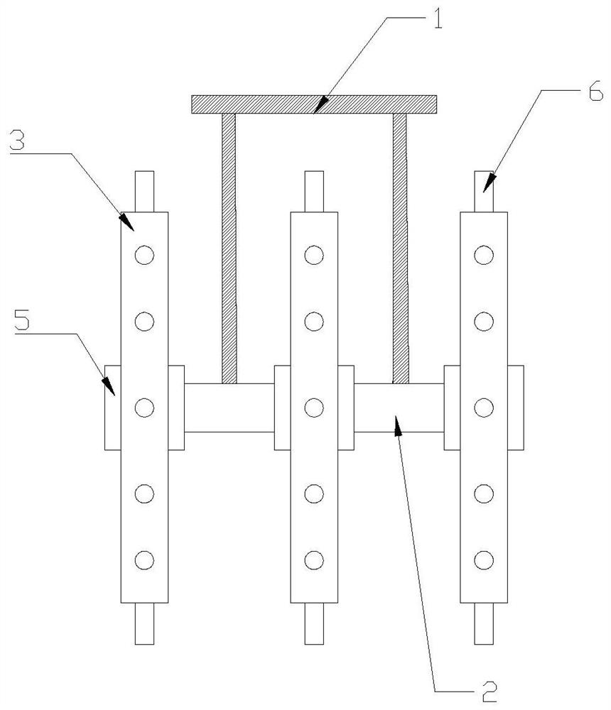
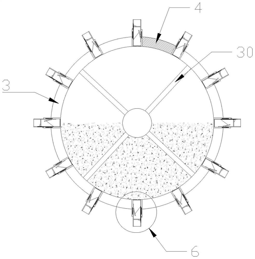
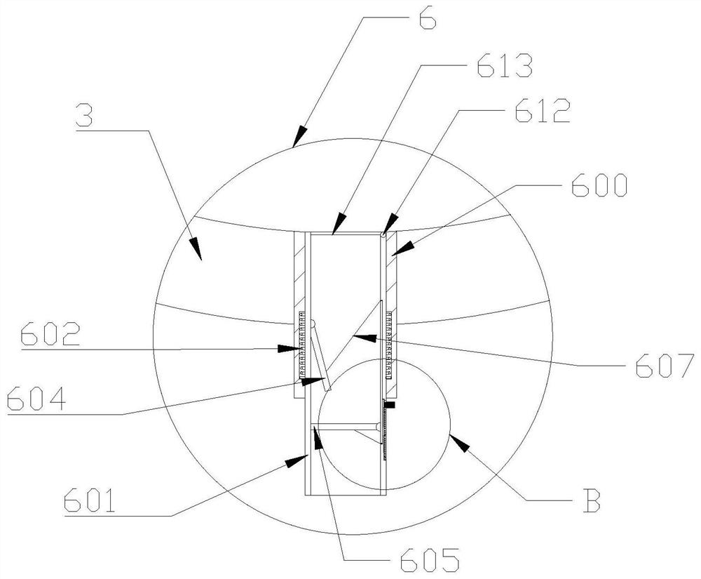
[0040] see Figure 1-3 and Figure 6 , a fertilizing device for corn cultivation in Example 1 of the present invention, comprising: a handrail 1, a support shaft 2 and a plurality of annular material cylinders 3, and the annular material cylinder 3 is provided with a feed cover 4, wherein the The handrail 1 is connected to the support shaft 2, the annular material cylinder 3 is sleeved on the support shaft 2 through the bearing 5, and the handrail 1 and the annular material cylinder 3 do not touch each other, along the The outer wall of the annular material cylinder 3 is provided with several discharge devices 6 in the circumfere...


PUM


Abstract

The invention belongs to the technical field of agricultural machineries, and particularly relates to a fertilizing device and fertilizing process for corn cultivation. The fertilizing device comprises a handrail, a support shaft and a plurality of annular material cylinders, the annular material cylinders are provided with feeding plates, the handrail is connected to the support shaft, the annular material cylinders are arranged on the support shaft in a sleeving manner through bearings, and the handrail does not make contact with the annular material cylinders; and a plurality of dischargingdevices are arranged in the circumferential direction of the outer walls of the annular material cylinders, and the discharging devices are connected with the annular material cylinders in a communicating mode; According to the fertilizing device, the plurality of material cylinders are arranged on the support shaft according to the row spacing of plants, so that multi-channel simultaneous fertilization is realized, the fertilization speed is increased, and the fertilization efficiency is improved; the plurality of discharging devices are arranged on the circumferential outer walls of the material cylinders according to the plant spacing, so that an intermittent fertilization mode is realized, and the fertilizer can be fully absorbed by plants; and the device is simple in structure and high in operability.

Description

technical field [0001] The invention belongs to the technical field of agricultural machinery, and in particular relates to a fertilization device and a fertilization process for corn cultivation. Background technique [0002] Corn is an important food product and has a wide range of planting. When planting corn, there will be a blank row with a width of about 1 meter between each row of corn. Corn needs a lot of nutrients to promote its rapid growth during the growth process. Reasonable fertilization is an important measure to achieve high yield, stable yield and low cost. [0003] But existing fertilization device has the following problems: [0004] 1. At present, the fertilization device mostly adopts the method of single-channel fertilization, the fertilization speed is slow, the efficiency is low, and at the same time, the amount of fertilization cannot be controlled according to the needs, resulting in waste of chemical fertilizers and increased costs; [0005] 2. W...

Claims


Application Information

Patent Timeline
Patent Type & Authority Applications(China)
IPC IPC(8): A01B49/06A01C15/02A01C15/00A01G25/09B01F7/04
CPCA01B49/06A01C15/02A01C15/005A01G25/09B01F27/70
Inventor 谢亚杰赵前军段海明余海兵
Owner ANHUI SCI & TECH UNIV
Why Eureka
Eureka Blog
Learn More