Hole type topdressing machine

The technology of a top dressing device and a fertilizer box is applied in the direction of direct liquid fertilizer conveying system, agricultural gas emission reduction, etc., which can solve the problems of insufficient top dressing effect, low work efficiency, low work efficiency, etc. Avoid repeated manual adjustments and improve work efficiency

Inactive Publication Date: 2015-06-03
赵刚
View PDF7 Cites 0 Cited by
  • Summary
  • Abstract
  • Description
  • Claims
  • Application Information

AI Technical Summary

Problems solved by technology

[0003] The present invention solves the problem that when the existing fertilization methods fertilize high-stalk crops such as corn and sorghum, manual fertilization has high labor intensity and low work efficiency, and the effect of deep topdressing cannot be achieved.
Semi-mechanical fertilization has a low working efficiency and cannot meet the needs of large-scale fertilization operations. Although the fertilization efficiency of the seeder is high, it cannot achieve the purpose of deep topdressing. A hole-type topdressing machine is proposed.

Method used


Image

  • Hole type topdressing machine
  • Hole type topdressing machine
  • Hole type topdressing machine

Examples


specific Embodiment approach 1

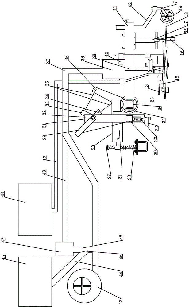
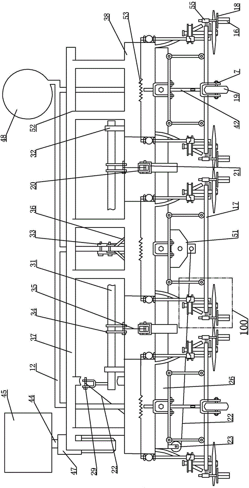
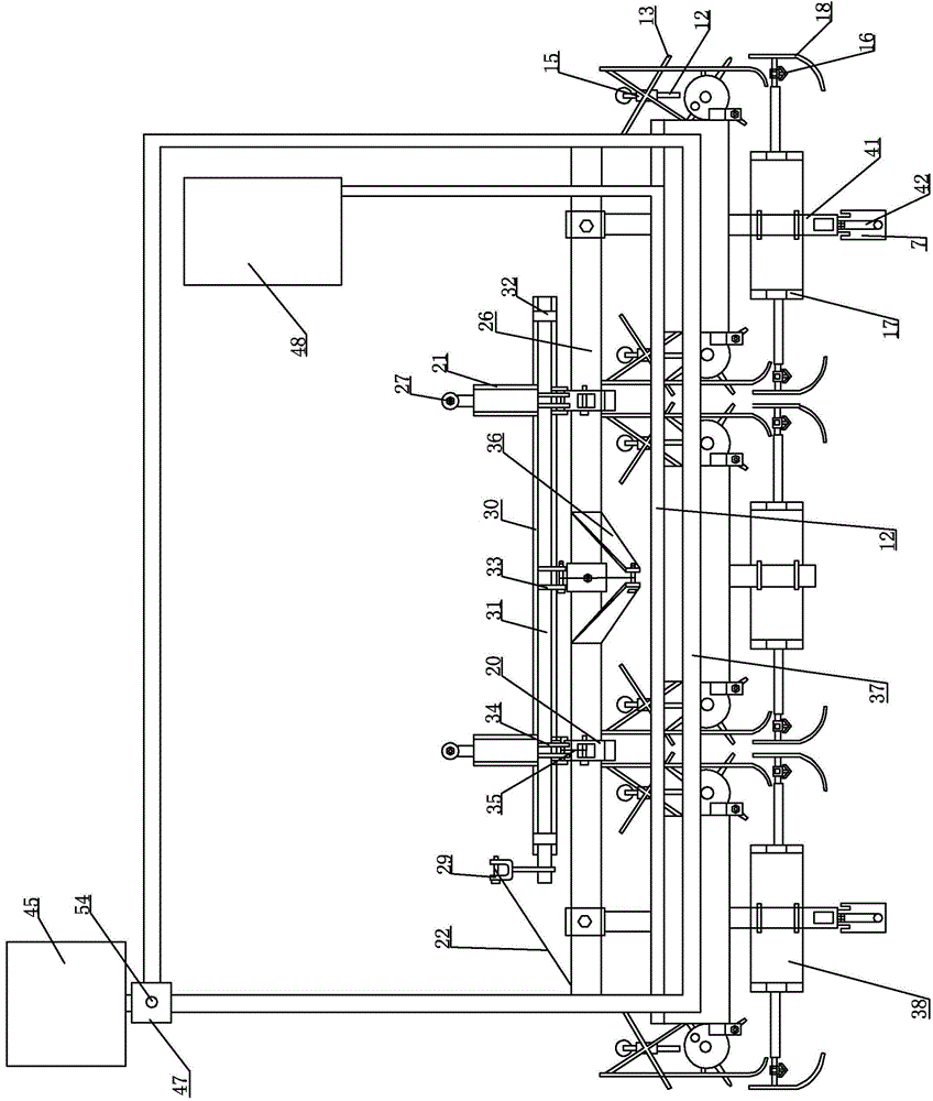
[0019] Specific implementation mode one: combine figure 1 , figure 2 and image 3 Illustrate the present embodiment, the cave type topdressing machine of the present embodiment, it comprises suspension mechanism, main frame crossbeam 26, main frame mechanism, multiple groups of ditching mechanism, topdressing mechanism and liquid mechanism, and described main frame mechanism and suspension mechanism are arranged respectively On both sides of the front and back of the main frame beam 26, the ditching mechanism is arranged on the lower end of the main frame mechanism, the topdressing mechanism is arranged on the main frame mechanism between the ditching mechanism and the main frame beam 26, and the liquid mechanism is arranged On the main frame mechanism between the topdressing mechanism and the main frame beam 26,

[0020] Described suspension mechanism comprises profile vertical support arm 27, profile arm base 21, balance spring 28, profile frame beam 30, fixed pulley 23, ...

specific Embodiment approach 2

[0029] Specific implementation mode two: combination Figure 4 and Figure 5 Describe this embodiment, each group of top dressing devices 100 described in this embodiment includes a first top dressing device, and the first top dressing device includes a first fixed rotating shaft 101, a first fixed screw rod 102, a first top dressing device guide rod 103, a first top dressing device One upper fixed wheel 105, the first plucking and topdressing wheel 106, the first axle sleeve 107, the first lower fixed wheel 108 and a plurality of first connecting plates 1010, the first fixed rotating shaft 101 is horizontally arranged, and the first fixed The screw rod 102 vertically passes through the first fixed rotating shaft 101 and is fixed with the first fixed rotating shaft 101. The first top dressing guide rod 103 is horizontally fixed on the first fixed screw rod 102 through the first connecting plate 1010. The first The upper fixed wheel 105, the first plucking and topdressing whee...

specific Embodiment approach 3

[0030] Specific implementation mode three: combination Image 6 and Figure 7 Describe this embodiment, in this embodiment, each group of top dressing devices 100 includes a second top dressing device, and the second top dressing device includes a second fixed rotating shaft 201, a second fixed screw rod 202, a second top dressing device guide rod 203, The second upper fixed wheel 205, the second lower fixed wheel 208, the topdressing wheel 206, the second upper spring 207-1, the second lower spring 207-2, the second puller wheel 2011, the second topdressing shaft 2014, the second rotating shaft sleeve 2016, the second fertilizer outlet pipe 2017 and a plurality of second connecting plates 2010, the second fixed shaft 201 is arranged horizontally, the second fixed screw 202 passes through the second fixed shaft 201 vertically and is connected with the second fixed shaft 201 fixed, the guide rod 203 of the second top dressing device is horizontally fixed on the second fixing s...


PUM


Abstract

The invention relates to a topdressing machine, in particular to a hole type topdressing machine. The hole type topdressing machine aims to solve the problems that when fertilizer is applied to corns, sorghum and other high-stalk crops with an existing fertilizer applying mode, manual fertilizer application is large in labor intensity and low in working efficiency, and the topdressing effect cannot be achieved; a semi-mechanical fertilizer applying mode is low in working efficiency and cannot meet the large-area fertilizer applying operation, and a planter fertilizer applying mode cannot achieve the aim of hole type deep topdressing even the fertilizer applying efficiency is high. The hole type topdressing machine comprises a hanging mechanism, a body frame cross beam, a body frame mechanism, multiple sets of ditching mechanisms, a topdressing mechanism and a liquid mechanism, the body frame mechanism and the hanging mechanism are arranged on the front side and the rear side of the body frame cross beam respectively, the ditching mechanisms are arranged at the lower end of the body frame mechanism, the topdressing mechanism is arranged on the body frame mechanism between the ditching mechanisms and the body frame cross beam, and the liquid mechanism is arranged on the body frame mechanism between the topdressing mechanism and the main frame cross beam. The topdressing machine is used for applying the fertilizer to the corns, sorghum and other high-stalk crops.

Description

technical field [0001] The invention relates to a top dressing machine, in particular to a hole type top dressing machine. Background technique [0002] At present, for high-stalk crops such as corn and sorghum, there are mainly two methods of top dressing, manual and semi-mechanical. The manual method mainly uses manpower to spread fertilizer manually. The fertilization position of this manual method is inaccurate and wastes fertilizer. , the labor intensity is high, and the semi-mechanical method is divided into two types: injection fertilization and hole-digging fertilization. Although injection fertilization and hole-digging fertilization achieve the purpose of hole-type deep topdressing, the work efficiency is low, and it is only suitable for small-area operations and cannot meet the needs of corn fields. 1. In the fertilization of sorghum fields, in addition to the above methods of fertilization, seeders are also used for topdressing. Although the efficiency of fertili...

Claims


Application Information

Patent Timeline
Patent Type & Authority Patents(China)
IPC IPC(8): A01C23/02
CPCY02P60/21
Inventor 赵刚
Owner 赵刚
Why Eureka
Try Eureka