Vacuum-assisted post-grouting device and method for bored piles

A bored-in-place pile and vacuum-assisted technology, applied in sheet pile wall, construction, infrastructure engineering, etc., can solve the problems of disturbing the gravel layer, difficulty in judging the effect of grouting, difficulty in grouting, etc., so as to improve the bearing capacity of the pile body. ability, ensure the quality of post-grouting, and reduce the effect of post-grouting time

Active Publication Date: 2022-05-10
CHINA FIRST METALLURGICAL GROUP
View PDF0 Cites 0 Cited by
  • Summary
  • Abstract
  • Description
  • Claims
  • Application Information

AI Technical Summary

Problems solved by technology

[0003] At present, there are the following problems when grouting after bored piles: 1) The water-cement ratio should not be too large or too small. If it is too large, it will cause difficulty in grouting, and if it is too small, the cement slurry will form segregation under pressure; 2) The grouting often occurs along the side of the pile or in other parts, the grouting effect is difficult to judge and difficult to control, and the single pile grouting period is long; 3) The pressure control of the grouting process is cumbersome. The pre-set amount of grouting, but when it reaches a certain pressure, the grouting should be stopped. If the pressure of grouting is too high, it will cause the grout to segregate, block the pipeline, disturb the gravel layer, and even make the pile body float.

Method used


Image

  • Vacuum-assisted post-grouting device and method for bored piles
  • Vacuum-assisted post-grouting device and method for bored piles
  • Vacuum-assisted post-grouting device and method for bored piles

Examples


Embodiment Construction

[0028] The present invention will be further described below in conjunction with the accompanying drawings and embodiments.

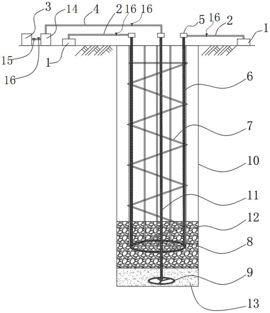
[0029] A vacuum-assisted post-grouting method for bored piles, such as figure 1 shown, including steps:

[0030] S1. Hole forming of bored piles—the hole depth, hole diameter and verticality are controlled during the construction process. Since a sand cushion layer 13 needs to be set at the bottom of the pile, it can be completed under the premise that the soil properties of the bearing layer are clear and the bearing capacity of the pile is not affected. The hole depth is one thicker than the designed drilling depth by the thickness of the sand cushion layer 13, and the thickness of the sand cushion layer 13 in this embodiment is 20-30 cm.

[0031] S2. Cleaning the hole for the first time - cleaning the pile hole and cleaning the residue in the drilling hole.

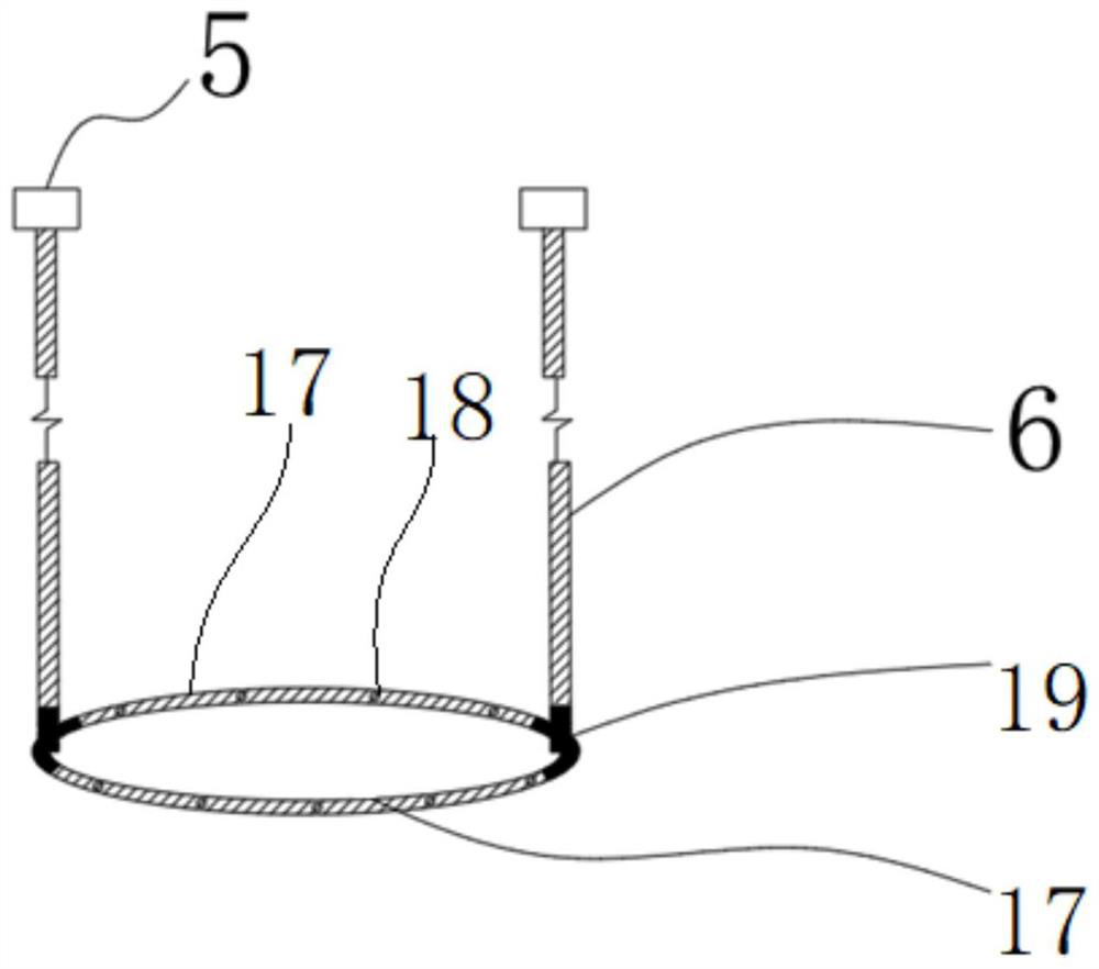
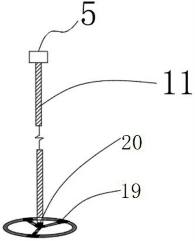
[0032] S3. Bind and fix the inner grouting pipe 6, the grouting device 8 and the inner vac...


PUM


Abstract

The invention discloses a vacuum-assisted grouting device and method for bored cast-in-situ piles, which include a grouting pump, an outer grouting pipe, an inner grouting pipe, a grouting device, a vacuum pump, a vacuum chamber, an outer vacuum pipe, an inner vacuum pipe and a negative Pressure device; grouting holes are distributed on the grouting device and located in the crushed stone layer, negative pressure holes are distributed on the negative pressure device and located in the sand cushion layer, the negative pressure holes on the negative pressure device are covered with anti-sand cloth, sand cushion Layers are laid at the bottom of the pile, gravel layers are laid on the sand cushion, the lower end of the inner grouting pipe is connected to the grouting device, and the upper end extends out of the pile hole to be detachably connected with the outer grouting pipe, and the lower end of the inner vacuum pipe is connected to the negative pressure device , After the upper end extends out of the pile hole, it can be detachably connected with the outer vacuum tube. The upper ends of the inner grouting tube and the inner vacuum tube can be closed by the cap. The inner grouting tube, the grouting device and the inner vacuum tube are connected to the steel cage, and the bottom of the steel cage The end is located in the gravel layer, valves are provided on the outer grouting pipe and the outer vacuum pipe, and a valve and a vacuum degree detection piece are provided between the vacuum pump and the vacuum chamber. The post-grouting quality of the invention is high.

Description

technical field [0001] The invention belongs to the field of pile foundation construction, and in particular relates to a vacuum-assisted post-grouting device and method for bored cast-in-place piles. Background technique [0002] The bearing layer of bored piles requires a relatively complete rock layer. When the bearing layer is a non-rock layer, the post-grouting method is generally used to strengthen the foundation at the pile end. Pile end grouting technology refers to: bury the grouted steel pipe along the outer wall of the pile reinforcement cage, and after the pile concrete strength meets the requirements, press the cement slurry through the steel pipe into the pores of the gravel layer at the pile end by pressure, so that the original bad holding force Layer, cemented into a high-strength combination, the cement slurry diffuses from the pile end in the pores of the gravel layer to the surrounding under pressure. The downward diffusion is equivalent to increasing th...

Claims


Application Information

Patent Timeline
Patent Type & Authority Patents(China)
IPC IPC(8): E02D5/34E02D5/62E02D15/04
CPCE02D5/34E02D5/62E02D15/04
Inventor 孔晓龙魏华杰刘小松陈世伟李兵张向辉董美华胡玉强王宇航董辉邬忠面
Owner CHINA FIRST METALLURGICAL GROUP
Why Eureka
Try Eureka