Vacuum grouting device for cast-in-situ bored pile and construction method

A bored-in-place pile and vacuum grouting technology, applied in sheet pile wall, foundation structure engineering, construction, etc., can solve the problem that the soil strength at the pile end cannot be effectively improved, the final effect of grouting cannot be judged, and the grouting is terminated. Time can not be determined and other problems, to achieve the effect of improving the utilization rate of pipe materials, filling the gaps and improving the grouting effect

Active Publication Date: 2021-03-09
CHINA FIRST METALLURGICAL GROUP
View PDF6 Cites 0 Cited by
  • Summary
  • Abstract
  • Description
  • Claims
  • Application Information

AI Technical Summary

Problems solved by technology

Defects in the construction process of grouting method after bored piles: 1. Excessive water-cement ratio will cause difficulty in grouting, blockage of grouting pipe, and failure to complete subsequent grouting work; too small water-cement ratio will make cement slurry under pressure Under segregation, the strength of the pile tip soil cannot be effectively improved
2. During the grouting process, the grouting will occur along the side of the pile or in other parts. The final effect of the grouting cannot be judged, the end time of the grouting cannot be determined, and the quality of the grouting is difficult to control

Method used


Image

  • Vacuum grouting device for cast-in-situ bored pile and construction method
  • Vacuum grouting device for cast-in-situ bored pile and construction method
  • Vacuum grouting device for cast-in-situ bored pile and construction method

Examples


Embodiment Construction

[0034] In order to make the object, technical solution and advantages of the present invention clearer, the present invention will be further described in detail below in conjunction with the accompanying drawings and embodiments. It should be understood that the specific embodiments described here are only used to explain the present invention, not to limit the present invention.

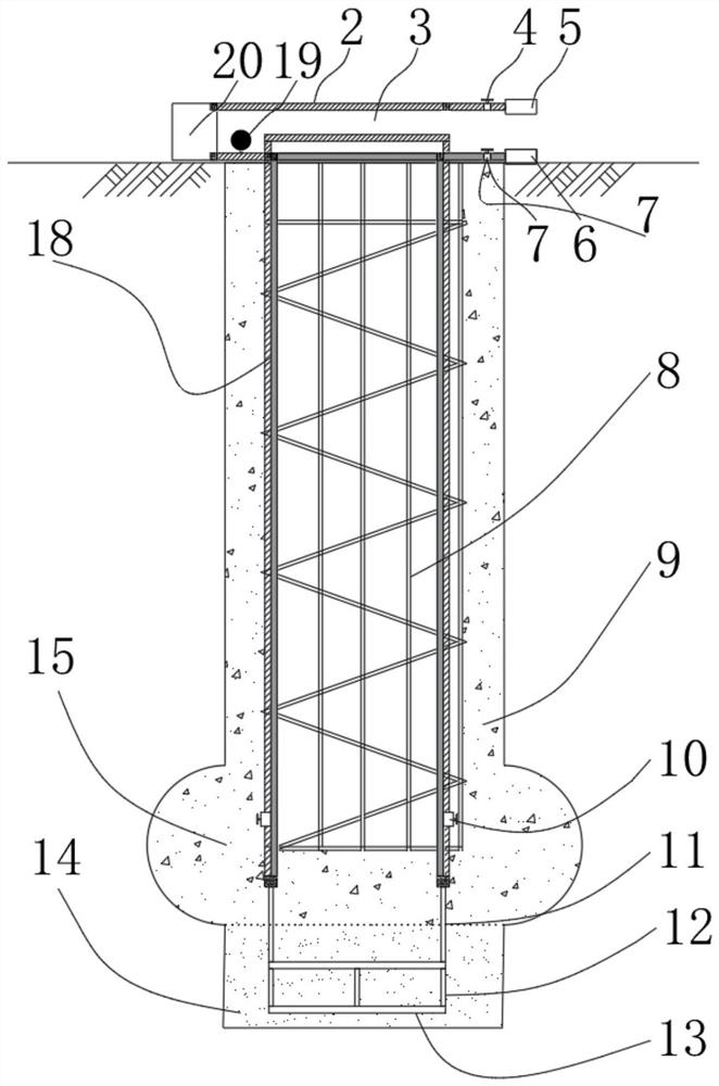
[0035] Such as figure 1 As shown, the vacuum grouting device for bored cast-in-place piles according to the embodiment of the present invention is used for vacuum grouting the cast-in-place piles, and the grout 9 is poured into the cast-in-place piles, and the cast-in-place piles are provided with steel cages 8, The bottom of the cast-in-place pile is provided with a sand cushion 14, and the sand cushion 14 is provided with a pile end reaming 15; wherein:

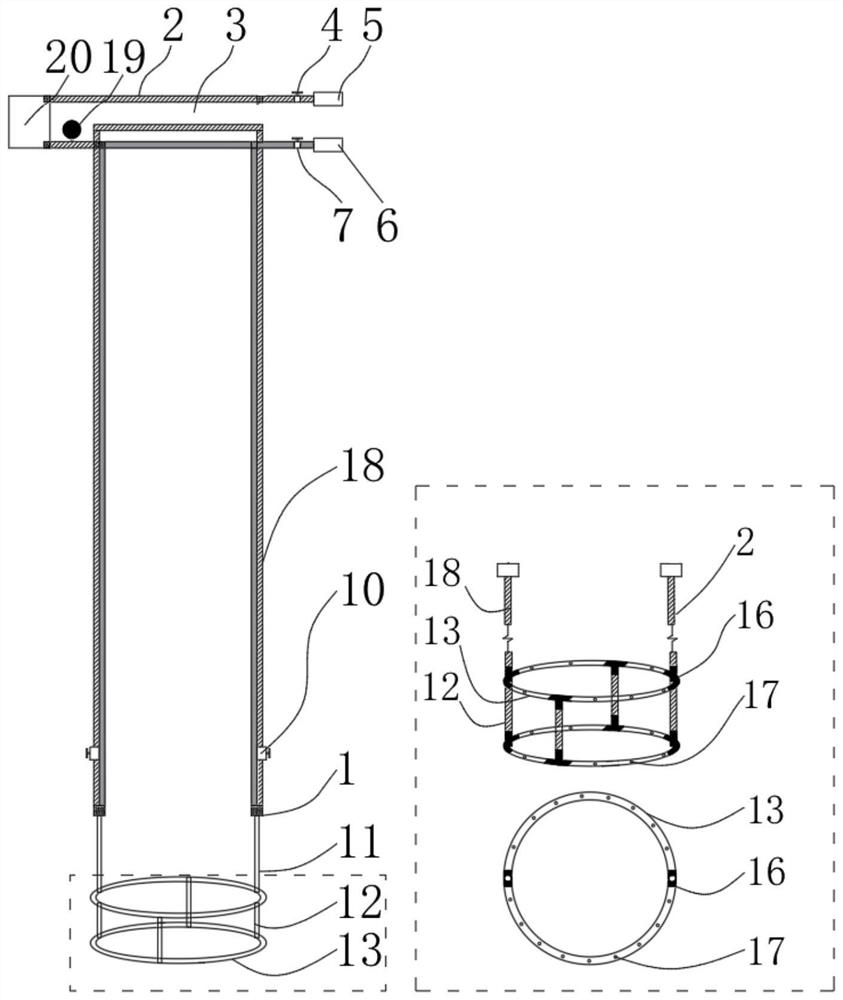
[0036] The vacuum grouting device includes vacuum grouting pipes 18 arranged on both sides of the reinforcement cage 8 in the cast-in-place pi...


PUM


Abstract

The invention discloses a vacuum grouting device for a cast-in-situ bored pile and a construction method. A vacuum pump and a grouting pump are arranged on the vacuum grouting device, a vacuum pipe valve is connected to the vacuum pump, and the vacuum pump is connected with the top end of a vacuum pipe through the vacuum pipe valve; a grouting valve is connected to the grouting pump, and the grouting pump is connected with the top end of a grouting pipe through the grouting valve; a pile tip grout connecting pipe, a pile tip vertical communicating pipe and a transverse communicating pipe are connected to the bottom end of the vacuum grouting pipe, and a plurality of pipe holes are formed in the pile tip transverse communicating pipe. The method comprises the following steps of, forming a hole of the cast-in-situ bored pile; enlarging the hole at the pile tip and the pile bottom; cleaning the hole for the first time; manufacturing a reinforcement cage and installing the vacuum groutingdevice; cleaning the hole for the second time; pouring the cast-in-place pile; maintaining the pile body; Vacuumizing the pile tip to remove water vapor at the pile tip; grouting and reinforcing the pile tip; stopping grouting; and carrying out checking and acceptance. According to the vacuum grouting device and the construction method, the pile tip grouting effect is improved; and the grout is fully diffused to the periphery of the pile tip, the bearing area of the pile tip is increased, and the pile tip soil body strength and the pile body bearing capacity are improved.

Description

technical field [0001] The invention relates to the technical field of cast-in-situ pile construction, in particular to a vacuum grouting device and construction method for bored cast-in-situ piles. Background technique [0002] With the rapid development of high-rise buildings and bridges in my country, the requirements for the bearing capacity of building foundations are getting higher and higher. The foundation form generally adopts bored piles, and the bearing layer is required to be a relatively complete rock layer, and the pile diameter is long. Larger size requirements. After years of practice and research, Chinese researchers have used the post-grouting method to solve the problem of insufficient bearing capacity of pile tips when the bearing layer of the foundation is in a non-rock state, and have achieved good economic benefits. Post-grouting method refers to: the grouted steel pipe is hoisted to the bottom of the pile together with the steel cage. After the pile b...

Claims


Application Information

Patent Timeline
Patent Type & Authority Applications(China)
IPC IPC(8): E02D15/04E02D5/34
CPCE02D15/04E02D5/34
Inventor 孔晓龙历洪岩刘志张龙姚世雄刘小松弓建春胡擎柱陈世伟王赛向万里
Owner CHINA FIRST METALLURGICAL GROUP
Why Eureka
Try Eureka