Pavement crack sealing device for road construction

A technology for road construction and joint filling, applied in roads, roads, road repairs, etc., can solve the problems of low cement concrete bearing capacity, broken concrete pavement, subsidence, heat loss and hardening of asphalt materials, etc., to improve grouting efficiency , improve the use of limitations, reduce the effect of heat loss

Inactive Publication Date: 2018-07-20
山西云度知识产权服务有限公司
View PDF7 Cites 11 Cited by
  • Summary
  • Abstract
  • Description
  • Claims
  • Application Information

AI Technical Summary

Problems solved by technology

[0002] As we all know, due to the physical changes of thermal expansion and contraction, when building new cement concrete roads, in order to ensure that the cement concrete roads will not be damaged under the condition of temperature changes, expansion joints are set between the cement blocks, and fillers are filled in the expansion joints After a period of use of cement concrete roads, the fillers in the expansion joints age and deteriorate, and the accumulated water on the road continuously flows into the expansion joints, causing the foundation of the cement concrete road to sink, resulting in lower and lower bearing capacity of the cement concrete. , resulting in broken boards, collapse and other diseases on the concrete pavement, which seriously affects traffic safety. The road surface filling device for road construction is a kind of grouting for road expansion joints in the process of road construction and maintenance, so as to facilitate better maintenance of the road surface. An accessory device, which has been widely used in the field of road surface maintenance in road construction; the existing road surface filling de

Method used


Image

  • Pavement crack sealing device for road construction
  • Pavement crack sealing device for road construction
  • Pavement crack sealing device for road construction

Examples


Example Embodiment

[0018] The specific embodiments of the present invention will be described in further detail below in conjunction with the drawings and embodiments. The following examples are used to illustrate the present invention, but not to limit the scope of the present invention.

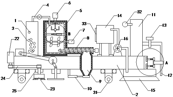
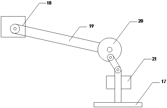
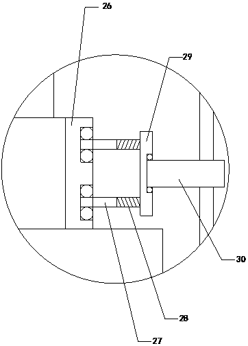
[0019] Such as Figure 1 to Figure 4 As shown, a pavement joint grouting device for road construction of the present invention includes asphalt material 1; including bottom plate 2, material holding tank 3, suction pipe 4, hot melt kettle 5, first mixing motor 6, and second mixing motor 7. Screw conveyor 8, discharging gun 9 and second hydraulic cylinder 10. The material tank is installed on the left side of the top of the bottom plate, and the bottom end of the material tank is connected with the top of the bottom plate. The hot melt kettle is located at the top of the bottom plate. On the right side, there is a partition inside the hot melt kettle. The partition divides the hot melt kettle into an upper stora...


PUM


Abstract

The invention relates to the technical field of auxiliary devices for road construction and pavement maintenance, in particular to a pavement crack sealing device for road construction. The pavement crack sealing device is capable of mixing and melting asphalt materials by self so as to reduce heat loss and to improve filling effect, and is also capable of automatically clearing litter from an expansion joint. The pavement crack sealing device comprises the asphalt materials, a bottom plate, a material placement tank, a material suction pipe, a hot melt kettle, a first mixing motor, a second mixing motor, a screw conveyor, a material discharging gun and a second hydraulic cylinder, wherein a partition plate is arranged inside the hot melt kettle; the partition plate divides the hot melt kettle into a material storage chamber and a material mixing chamber; a first transmission shaft is arranged at the bottom output end of the first mixing motor; the first transmission shaft is providedwith first mixing blades; a second transmission shaft is arranged at the left output end of the second mixing motor; and the second transmission shaft is provided with second mixing blades. The pavement crack sealing device also comprises an air compressor and a nozzle, wherein the bottom end of the air compressor is connected to the top end of the bottom plate; the air compressor is connected tothe nozzle through an air pipe; and a pressure reducing valve is arranged on the air pipe.

Description

technical field [0001] The invention relates to the technical field of road construction and road surface maintenance attachments, in particular to a road surface joint filling device for road construction. Background technique [0002] As we all know, due to the physical changes of thermal expansion and contraction, when building new cement concrete roads, in order to ensure that the cement concrete roads will not be damaged under the condition of temperature changes, expansion joints are set between the cement blocks, and fillers are filled in the expansion joints After a period of use of cement concrete roads, the fillers in the expansion joints age and deteriorate, and the accumulated water on the road continuously flows into the expansion joints, causing the foundation of the cement concrete road to sink, resulting in lower and lower bearing capacity of the cement concrete. , resulting in broken boards, collapse and other diseases on the concrete pavement, which serious...

Claims


Application Information

Patent Timeline
IPC IPC(8): E01C23/09
CPCE01C23/096
Inventor 袁晓艳
Owner 山西云度知识产权服务有限公司
Why Eureka
Try Eureka