Determination method for width and depth of pavement crack based on ground penetrating radar and rapid maintenance method

A technology of ground penetrating radar and pavement cracks, applied in road repair, on-site coagulation pavement, roads, etc., can solve the problems of unable to form tight continuous detection, difficult to achieve detection purpose, and weak evaluation representative. Achieve good social and economic benefits, improve grouting effect, and have the effect of strong applicability

Inactive Publication Date: 2019-03-08
JIANGSU SINOROAD ENG TECH RES INST CO LTD +1
View PDF3 Cites 11 Cited by
  • Summary
  • Abstract
  • Description
  • Claims
  • Application Information

AI Technical Summary

Problems solved by technology

[0002] At present, the detection of road pavement cracks and diseases mostly depends on the traditional drilling and coring method, which has the advantage of being intuitive, but the disadvantage is the destructive impact on the road, low frequency, slow speed, and cannot form a close continuous detection and evaluation The representativeness is not strong, and it is difficult to comprehensively find hidden quality problems, so it is difficult to achieve the ideal detection purpose

Method used


Image

  • Determination method for width and depth of pavement crack based on ground penetrating radar and rapid maintenance method
  • Determination method for width and depth of pavement crack based on ground penetrating radar and rapid maintenance method
  • Determination method for width and depth of pavement crack based on ground penetrating radar and rapid maintenance method

Examples


Embodiment 1

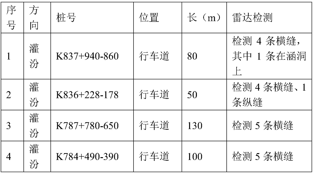
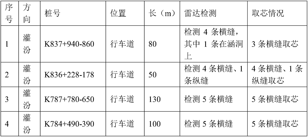
[0027] Example 1 Fenguan Expressway Disease Detection

[0028] Combined with the pavement structure of Fenguan Expressway, four sections were selected for radar detection through on-site investigation. The specific operation steps are as follows:

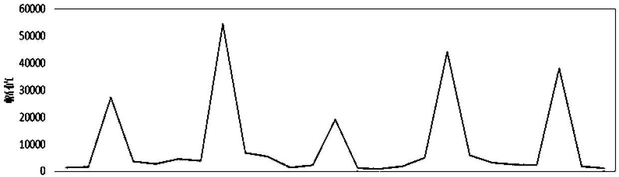
[0029] S1. Using ground penetrating radar to use high-frequency electromagnetic waves with a main frequency of 10M-1000M in the form of broadband short pulses, sent from the ground to the ground through the transmitting antenna, and returning to the ground after being reflected by the underground stratum or the target object, and received by the ground receiving antenna , through the imaging analysis of the receiving wave field, the radar waveform image of the underground target is obtained, and the radar waveform image is converted into a grayscale image;

[0030] S2. Judging the width of cracks on the road surface according to the magnitude of the grayscale image, the larger the magnitude of the grayscale image, the larger the wid...

Embodiment 2

[0039] Example 2. Disease detection of different highways

[0040] Using the same detection method as in Example 1, select the passages with abnormal signals inside the road surface in the ground-penetrating radar image at high speeds such as Shanghai-Nanjing, Zhenli, Ninghang, Ningsu-Xu, and coastal areas for coring verification. The verification results are shown in the following table:

[0041] Table 3 Radar detection results of different highway diseases

[0042]

[0043] (1) Coring verification at K240+220 in the direction of Ninghu (loose)

[0044] Radar image analysis: the reflection signal from the lower part of the base is relatively strong, and there is a slanted strengthened event, and the positive and negative take-offs are repeated, and there is a certain depth. It is preliminarily judged that the lower part of the base is seriously loose.

[0045] The description of the core sample taken here: the surface layer is intact, the lower part of the base layer is s...

Embodiment 3

[0068] Example 3. Calculation of crack width by radar detection

[0069] Taking the Shanghai-Nanjing Expressway as an example, the specific operation steps are as follows:

[0070] (1) Use ground penetrating radar to detect road cracks to obtain radar waveform images, and convert radar waveform images into grayscale images;

[0071] (2) analyze the amplitude of the grayscale image, judge the crack width of the pavement according to the amplitude, calculate the crack width according to the formula D=0.0002A-2.047, where D is the crack width, and the unit is mm; A is the amplitude;

[0072] The test results are as follows:

[0073] Table 4 Calculation results of crack width based on radar detection

[0074]

[0075] The radar detection value is verified by on-site coring, and the verification results are as follows:

[0076] Table 5 On-site coring verification results

[0077]

[0078]

[0079] According to the above verification results, it can be seen that the cal...


PUM


Abstract

The invention discloses a determination method for the width and the depth of a pavement crack based on a ground penetrating radar and a rapid maintenance technology, and belongs to the technical field of roadbed and pavement detection and maintenance. According to the key points of the technical scheme, the determination method for the width and the depth of the pavement crack based on the groundpenetrating radar comprises the following steps that S1, the ground penetrating radar is adopted to detect the pavement crack so as to obtain a radar waveform image, and the radar waveform image is converted into a gray level image; S2, the width of the pavement crack is judged according to the analyzed magnitude of the amplitude value of the gray level image, and the larger the amplitude value of the gray level image is, the larger the width of the crack is; and S3, a reflected signal of the gray level image is analyzed, the abnormal position of the reflected signal is judged, and the development level and the depth of the crack are determined. The determination method and the rapid maintenance technology have the advantage that rapid, nondestructive and continuous detection of the widthand the depth of the pavement crack is realized, so that maintenance personnel can conveniently take reasonable and scientific maintenance measures in time .

Description

technical field [0001] The invention belongs to the technical field of subgrade and pavement detection, maintenance and repair, and in particular relates to a method for determining the width and depth of cracks in a road surface based on ground penetrating radar and a rapid maintenance technology. Background technique [0002] At present, the detection of road pavement cracks and diseases mostly depends on the traditional drilling and coring method, which has the advantage of being intuitive, but the disadvantage is the destructive impact on the road, low frequency, slow speed, and cannot form a close continuous detection and evaluation The representativeness is not strong, and it is difficult to comprehensively discover quality hidden dangers, so it is difficult to achieve the ideal detection purpose. Contents of the invention [0003] The purpose of the present invention is to solve the problems existing in the detection of cracks in the subgrade and pavement, and propo...

Claims


Application Information

Patent Timeline
Patent Type & Authority Applications(China)
IPC IPC(8): E01C23/01E01C7/18
CPCE01C7/187E01C23/01
Inventor 金光来蔡文龙刘海婷许欢茅荃陆海珠祝争艳尹龙张晶
Owner JIANGSU SINOROAD ENG TECH RES INST CO LTD
Why Eureka
Try Eureka