
Mixing device for grout in inlet well at ground and application method thereof

A mixing device and grouting drilling technology, which is applied in earthwork drilling, wellbore/well components, sealing/isolation, etc., can solve the problems of grout waste, insufficient mixing of two kinds of grout, and affecting grouting effect, etc. Achieve the effect of avoiding security risks

Active Publication Date: 2016-02-10
SHANDONG UNIV
View PDF6 Cites 9 Cited by
  • Summary
  • Abstract
  • Description
  • Claims
  • Application Information

AI Technical Summary

Problems solved by technology

However, because the cement-sodium silicate grout mixing and pouring technology in the borehole has not been solved, a simple orifice mixing process is adopted. In deep hole grouting, the grout after mixing is too late due to the long distance of grout delivery. When entering the injected formation, the initial setting time is reached, and the grout solidifies in the borehole, resulting in a grouting accident that blocks the borehole; some even use the in-hole mixing process, but because the design of the mixing device is unscientific and unreasonable, resulting in two kinds of grout Insufficient mixing, it is difficult to achieve complete reaction after mixing the two kinds of grout, which not only affects the reaction quality of the grout, affects the grouting effect, but also causes a lot of waste of grout

Method used


Image

  • Mixing device for grout in inlet well at ground and application method thereof
  • Mixing device for grout in inlet well at ground and application method thereof
  • Mixing device for grout in inlet well at ground and application method thereof

Examples


Embodiment Construction

[0032] Below in conjunction with accompanying drawing and specific embodiment the technical scheme of the present invention is further described:

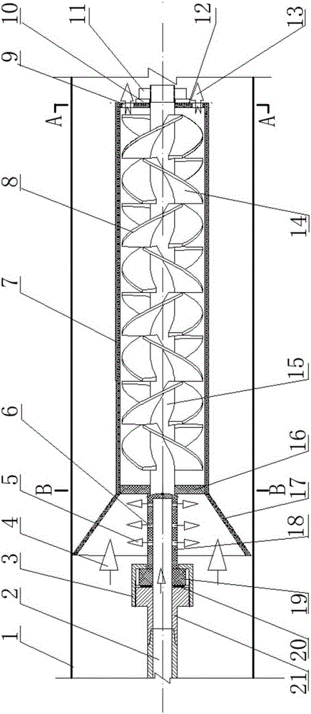
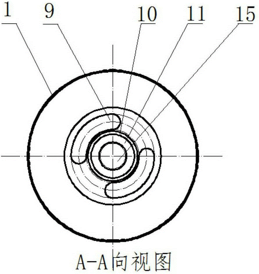
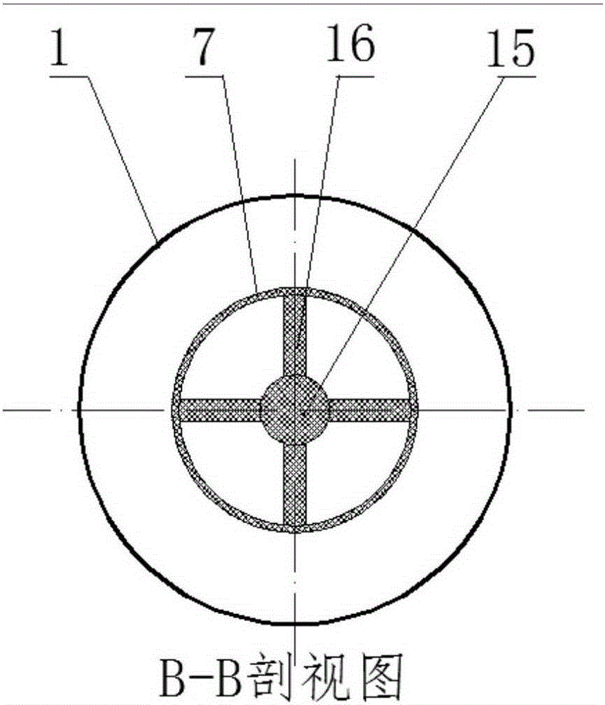
[0033] A grout mixing device in a ground grouting borehole, such as figure 1 As shown, it includes: a mandrel 15, a sheath and a slurry collector 17; the mandrel 15 is arranged inside the sheath, and the two ends of the mandrel 15 pass through the sheath; the bottom end of the mandrel 15 is fixed on the sheath, and the upper end passes through the sheath. The short pipe is connected to the drill pipe 2; the upper end of the sheath is connected to the slurry collector 17; right-handed blades and left-handed blades are alternately arranged on the mandrel 15, and the starting positions of the right-handed blades and left-handed blades are both in the middle of their upper blades place.

[0034] The cement slurry 4 and the water glass slurry 5 are mixed through the slurry collector 17 and then enter the sheath. The swirl direction of ...


PUM


Abstract

The invention discloses a mixing device for grout in an inlet well at the ground and an application method thereof. The mixing device comprises a mandril, a protecting bush and a grout collector, wherein the mandril is arranged in the protecting bush, and two ends of the mandril move through the protecting bush; the bottom end of the mandril is fixed to the protecting bush, and the upper end of the mandril is connected to a drilling rod through a short tube; the upper end of the protecting bush is connected to the grout collector; rightward rotating blades and leftward rotating blades are correspondingly arranged on the mandril in a staggering manner; the rightward rotating blade and the leftward rotating blade are arranged from the middle positions of the corresponding previous blades. The mixing device has the beneficial effects that the three purposes of injection mixing, swirling and agitating mixing, and slitting mixing can be essentially achieved in theory; the grout of two types can be fully mixed and completely chemically reacted, and the grouting effect is obvious.

Description

Technical field: [0001] The invention relates to a slurry mixing device in a surface grouting borehole and a using method thereof. The utility model belongs to the field of mine, tunnel and other underground engineering, and utilizes ground drilling to grout the surrounding rock of deep underground engineering to stop water and reinforce the field. technical background: [0002] During the construction of mines, tunnels and underground projects, it is inevitable to encounter unfavorable geological bodies. Unfavorable geological bodies mainly include faults, collapse columns, karst and other geological structures and soft and broken surrounding rocks. The existence of these abnormal geological conditions provides a good space for the storage and movement of groundwater. Once these spaces are communicated in the construction of underground projects, water inrush will occur, and even natural disasters such as catastrophic water seepage, surrounding rock collapse, or water and ...

Claims


Application Information

Patent Timeline
IPC IPC(8): E21B33/13
Inventor 潘光明张庆松李术才张霄林春金杨磊闫成伟
Owner SHANDONG UNIV
Learn More