Shield tunnel segment backfill grouting construction method

A shield tunnel segment and wall grouting technology, which is applied in tunnels, tunnel linings, earthwork drilling and mining, etc., can solve the problems of excessive surface settlement, large filling coefficient, and low construction risk, and achieve improved compactness, The effect of low cost and low construction risk

Inactive Publication Date: 2018-07-27
CHINA CONSTR MUNICIPAL ENG +2
View PDF4 Cites 11 Cited by
  • Summary
  • Abstract
  • Description
  • Claims
  • Application Information

AI Technical Summary

Problems solved by technology

[0004] The purpose of the present invention is to provide a post-grouting construction method for the segment wall of a shield tunnel, which can effectively solve the problems of

Method used


Image

  • Shield tunnel segment backfill grouting construction method
  • Shield tunnel segment backfill grouting construction method

Examples


Embodiment 1

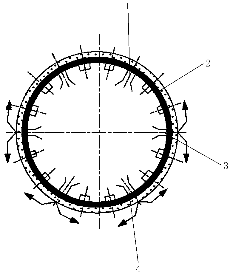
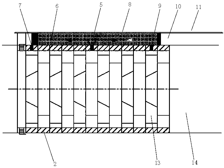
[0029] Embodiment 1: as figure 1 and figure 2 As shown, a post-grouting construction method for the segment wall of a shield tunnel comprises the following steps:

[0030] (1) In the construction tunnel 14, inject mortar below the middle part of the tunnel ring 2 formed by each segment 13 ( figure 1 , figure 2 The middle arrow indicates the flow direction of the mortar liquid), through the grouting pipes in the middle grouting hole 3 and the lower grouting hole 4 in the shield tail grouting hole, while the shield is advancing, the shield tail is formed by each segment Below the middle of the tunnel ring, press-inject mortar. Below the middle of the tunnel ring is the position below the horizontal diameter of the tunnel ring. Injecting mortar below the middle of the tunnel ring formed by the segments at the tail of the shield is to ensure that the gap space 10 between the segments below the middle and the tunnel soil layer 11 is filled densely, so as to prevent the segmen...

Embodiment 2

[0033] Embodiment 2: as figure 1 and figure 2 As shown, a post-grouting construction method for the segment wall of a shield tunnel comprises the following steps:

[0034] (1) Arrangement of the slurry-blocking net 8: a slurry-blocking net is provided between the segment and the tunnel soil layer. The grout blocking net is used to encapsulate the grout injected from the grouting hole reserved on the segment to ensure that the space between the segment and the tunnel soil is densely packed. The slurry-blocking net is made of iron, and the mesh diameter of the slurry-blocking net is smaller than or equal to the particle size of the sand in the mortar, encapsulating the injected slurry. The pulp blocking net is an iron net, or a net made of synthetic plastic, or a plastic cloth.

[0035] (2) Press-inject mortar into the grouting net below the middle part of the tunnel ring formed by each segment, and pass through the grouting pipe in the middle grouting hole 3 and the lower g...


PUM


Abstract

The invention belongs to a shield tunnel segment backfill grouting construction method. The method includes: a grout blocking net used for encapsulating grout injected from the reserved grouting holesin segments is arranged between each segment and a tunnel soil layer; compressively injecting mortar into the grout blocking nets below the middles of tunnel rings formed by the segments, and compressively injecting mortar into the grout blocking nets below the middles of tunnel rings formed by the segments at the shield tail through shield tail grouting holes during shield tunneling; injecting double-grout for sealing into gaps between 10 segment rings and the grout blocking nets through reserved annular sealing grouting holes in the segments above the middle of the 10th ring every other 10segment rings to form front sealing rings, and then injecting supplementary mortar into gaps between the segments between two sealing rings and the tunnel soil layer through reserved grouting holes inthe top of the fifth segment ring. By the method which is low in construction risk, low in cost, capable of shortening construction period and good in use effect, the problems of large filling coefficient, incompactness and excessively large ground surface settlement can be solved effectively.

Description

technical field [0001] The invention belongs to a post-grouting construction method for a segment wall of a shield tunnel. Background technique [0002] At present, as an advanced construction method, the shield tunneling method has been more and more widely used in the construction of underground tunnels because of its fast construction speed, high degree of safety, less disturbance to the ground, and applicable to various complex strata. . Shield construction technology is more and more widely used in underground engineering in my country, and has become the main method of cross-river tunnel construction. After the shield machine is excavated, there will be a certain gap between the segment and the stratum, and between the segment and the shield tail shell. In order to control the deformation of the stratum, reduce the settlement, and improve the impermeability of the tunnel and the early stage of the segment lining Stability requires filling slurry behind the segment wa...

Claims


Application Information

Patent Timeline
IPC IPC(8): E21D11/10E21D11/08E21D11/38
CPCE21D11/08E21D11/10E21D11/385
Inventor 陈俐光姜涌于艺林田辉陈通亮孟苏坪张雪油新华邓美龙
Owner CHINA CONSTR MUNICIPAL ENG
Why Eureka
Try Eureka