
Optical fiber sensor system for monitoring well wall and deformation early warning method

An optical fiber sensor and sensor technology, which is used in the use of optical devices to transmit the direction of sensing components, instruments, measuring devices, etc.

Pending Publication Date: 2018-10-09
ANHUI UNIV OF SCI & TECH +1
View PDF7 Cites 19 Cited by
  • Summary
  • Abstract
  • Description
  • Claims
  • Application Information

AI Technical Summary

Problems solved by technology

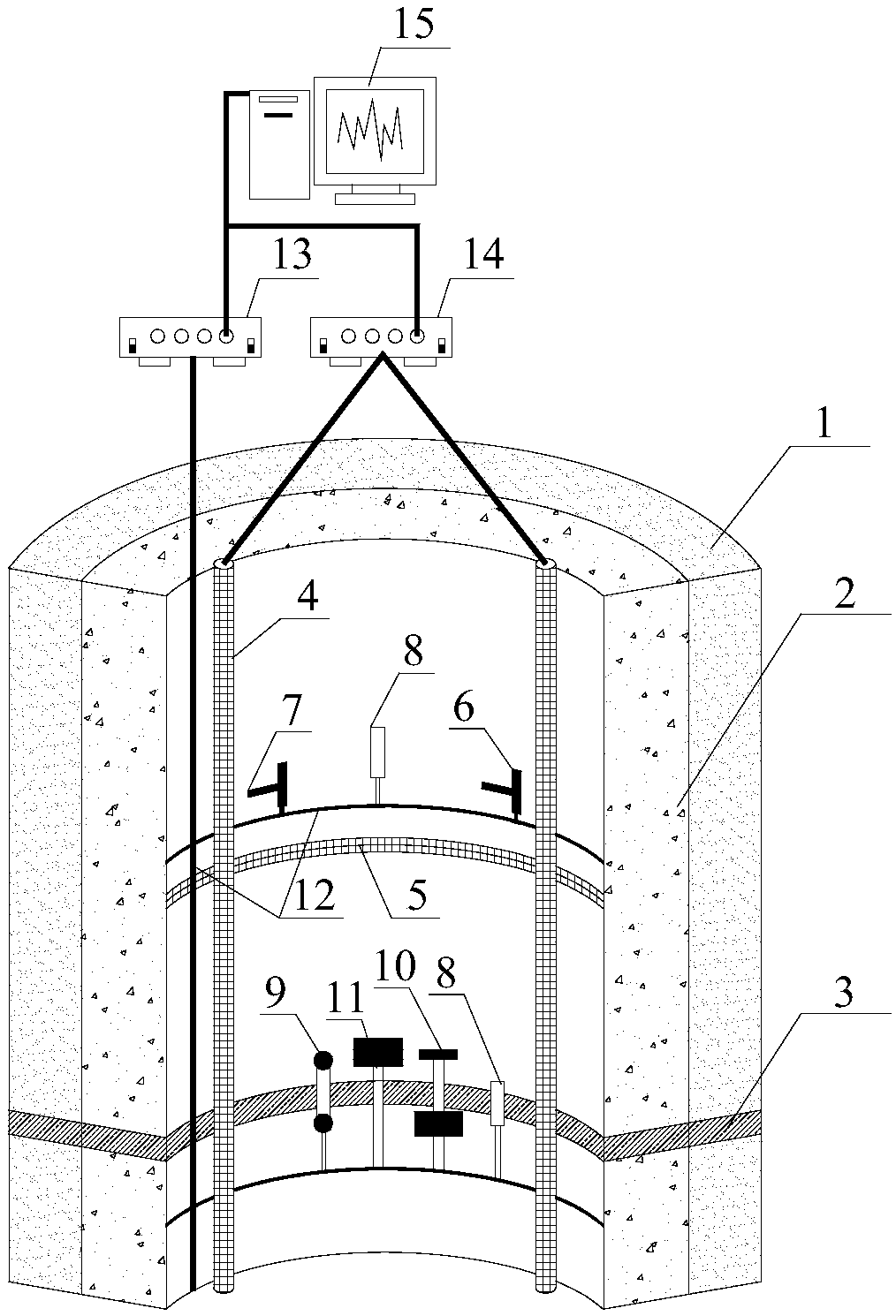
[0004] The purpose of the present invention is to provide an optical fiber sensor system for monitoring the borehole wall and a method for early warning of deformation. The technical solution of the present invention solves the monitoring problem of the borehole wall during the reinforcement and grouting process of deep shaft formations under existing wellbore conditions, and provides A method for determining the early warning value of wellbore deformation based on the current stress condition of the wellbore is proposed, which can fill in the gaps that there is no monitoring system for deep shaft formation reinforcement grouting and a method for determining the early warning value of deformation under existing wellbore conditions. An important part of the fracture comprehensive treatment plan, which ensures the safe production of the mine during the comprehensive treatment period, greatly improves the safety of deep vertical shaft formation reinforcement grouting, and greatly reduces construction risks, with remarkable social and economic benefits

Method used


Image

  • Optical fiber sensor system for monitoring well wall and deformation early warning method
  • Optical fiber sensor system for monitoring well wall and deformation early warning method
  • Optical fiber sensor system for monitoring well wall and deformation early warning method

Examples


Embodiment Construction

[0073] The present invention will be described in detail below with reference to the accompanying drawings and examples. Each example is provided by way of explanation of the invention, not limitation of the invention. In fact, those skilled in the art will recognize that modifications and variations can be made in the present invention without departing from the scope or spirit of the invention. For example, features illustrated or described as part of one embodiment can be used on another embodiment to yield a still further embodiment. Therefore, it is intended that the present invention includes such modifications and variations as come within the scope of the appended claims and their equivalents.

[0074] In the description of the present invention, the terms "longitudinal", "transverse", "upper", "lower", "front", "rear", "left", "right", "vertical", "horizontal", " The orientations or positional relationships indicated by "top", "bottom", etc. are based on the orienta...


PUM


Abstract

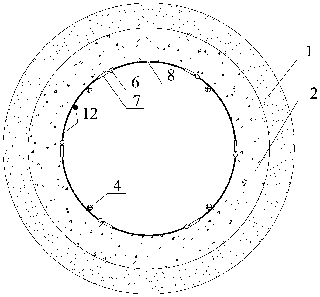
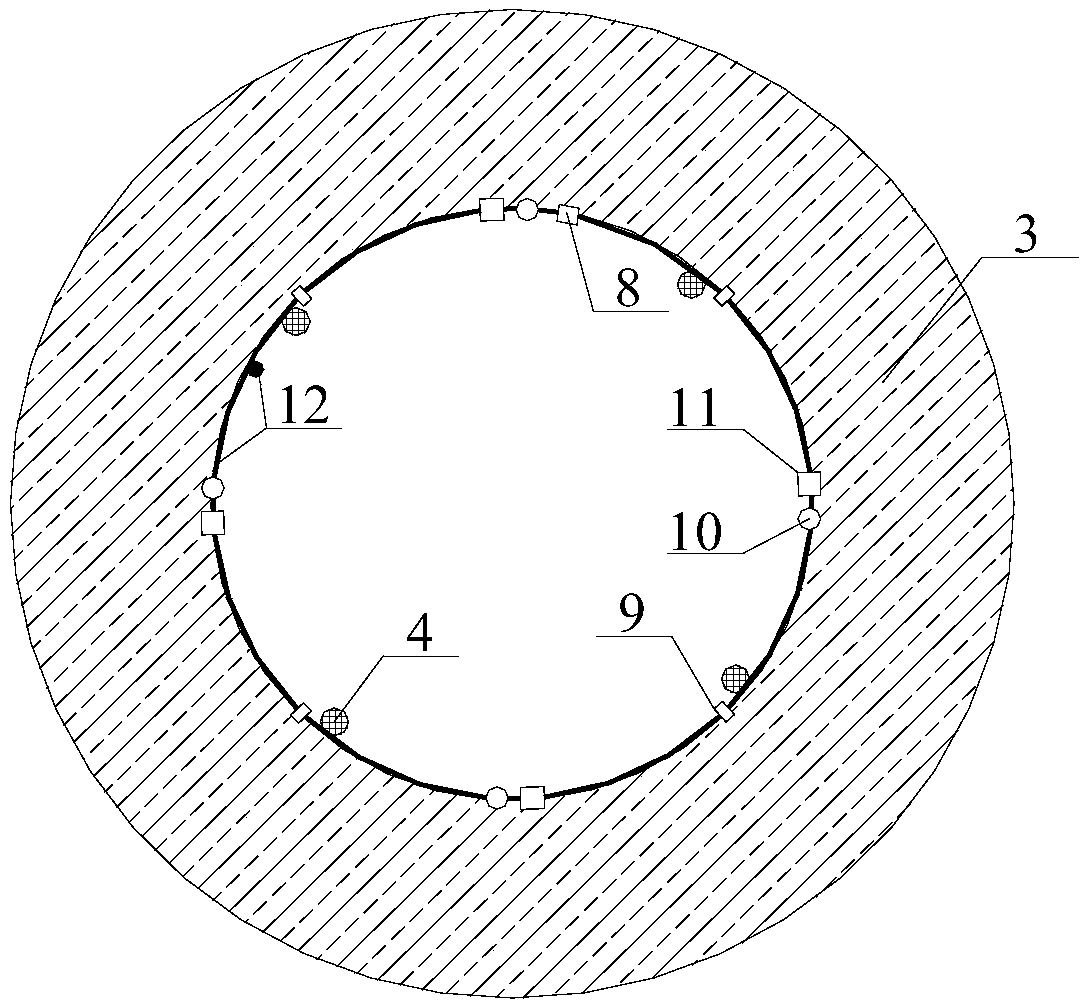
The invention provides an optical fiber sensor system for monitoring a well wall and a deformation early warning method. The optical fiber sensor system comprises distributed optical fiber sensors, fiber bragg grating strain sensors, external fiber bragg grating temperature sensors, an optical cable, a distributed optical fiber demodulation instrument, a fiber bragg grating demodulation instrumentand a computer. The several distributed optical fiber sensors, the several fiber bragg grating strain sensors and the several external fiber bragg grating temperature sensors are arranged on the internal surface of the well wall. The several distributed optical fiber sensors are connected to the distributed optical fiber demodulation instrument through the optical cable. The distributed optical fiber demodulation instrument is connected to the computer. The fiber bragg grating strain sensors and the external fiber bragg grating temperature sensors are connected to the fiber bragg grating demodulation instrument through the optical cable. In the invention, grouting pressure on the inner layer of the well wall , the deformation of the inner layer of the well wall and a well wall temperaturecan be monitored.

Description

technical field [0001] The invention relates to the field of mine construction, in particular to an optical fiber sensor system for monitoring shaft walls and a deformation early warning method. Background technique [0002] Since the 1980s, a large number of mines in Datun, Xuzhou, Huaibei, Yanzhou, Yongxia and other mining areas have experienced shaft wall rupture disasters in thick topsoil layers. Some of them occurred during shaft construction, and some occurred after the mine was put into production. , the lighter ones stop work and stop production, and the more serious ones are permeable and flooded wells, which seriously restrict the further development of deep shaft construction in my country. The research on the mechanism of borehole wall fracture has formed the hypothesis of vertical additional force, the hypothesis of mining influence, and the hypothesis of neotectonic movement. The results of a large number of theoretical analysis, numerical simulation and field ...

Claims


Application Information

Patent Timeline
IPC IPC(8): G01D5/353G01B11/14G01B11/16G01B11/26G01B11/02G01K11/32
CPCG01B11/02G01B11/14G01B11/18G01B11/26G01D5/353G01K11/32
Inventor 程桦彭世龙荣传新姚直书王晓健孙家应余大有李华黎明镜唐彬张楠林键王志王彬段寅刘小虎
Owner ANHUI UNIV OF SCI & TECH
Learn More