Laser-high frequency induction composite welder and its method

A technology of laser welding and laser welding head, applied in laser-high frequency induction hybrid welding device and its fields, can solve the problems of formation of pores or voids, easy generation of cracks, adverse effects of base metal, etc., and eliminate the generation of pores and cracks. , to ensure stability and reliability, and to improve the overall performance of the weld

Inactive Publication Date: 2004-12-15
HUAZHONG UNIV OF SCI & TECH
View PDF0 Cites 35 Cited by
  • Summary
  • Abstract
  • Description
  • Claims
  • Application Information

AI Technical Summary

Problems solved by technology

However, while laser welding technology is widely used, it also has certain limitations: many metal materials have high reflectivity, low absorption rate and low energy utilization rate for laser; the laser has a short action time on the base material, and the molten metal solidifies quickly. Fast, especially in high aspect ratio welds or non-penetrating welding, the metal vapor in the weld and the inhaled ambient gas are not easy to escape completely, resulting in the formation of pores or cavities; the heat input of laser welding is much smaller than conventional methods , the cooling rate of the weld metal is very fast, so for materials such as medium-high carbon steel or high alloy, the martensitic hardened structure is very easy to appear in the weld and the welding heat-affected zone, which deteriorates the comprehensive performance of the welded joint and is prone to cracks
[0004] In foreign actual production, some people have used high-frequency induction and laser heat sources together to weld stainless steel pipes, that is, high-frequency induction is used to preheat the entire section of the pipe to be welded before laser welding, although it has improved joint penetration and performance. The effect of increasing the speed, but this device only uses high-frequency induction for preheating. The heating area includes not only the weld area, but also the base metal away from the weld. The large heat input will definitely expand the welding heat-affected zone, and may It has a certain adverse effect on the base metal; the preheating temperature cannot be monitored in real time. Once the process conditions change (such as the distance between the induction heating coil and the workpiece), the welding structure and performance will inevitably change. The stability and repeatability of the process Poor; and the device can only weld the pipe under the condition that the welded pipe moves in a straight line and the welding head (including the laser head and the induction heating coil) is fixed. 3D weld

Method used


Image

  • Laser-high frequency induction composite welder and its method
  • Laser-high frequency induction composite welder and its method

Examples


Embodiment Construction

[0019] In order to realize the laser-high frequency induction hybrid welding described in the present invention, a solid YAG or CO 2 A laser and an optical path capable of transmitting laser light, as well as a high-frequency induction heating device.

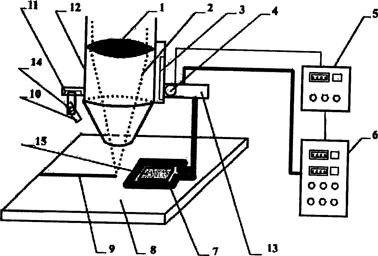
[0020] The implementation of laser-high frequency induction hybrid welding will be described below in conjunction with specific examples.

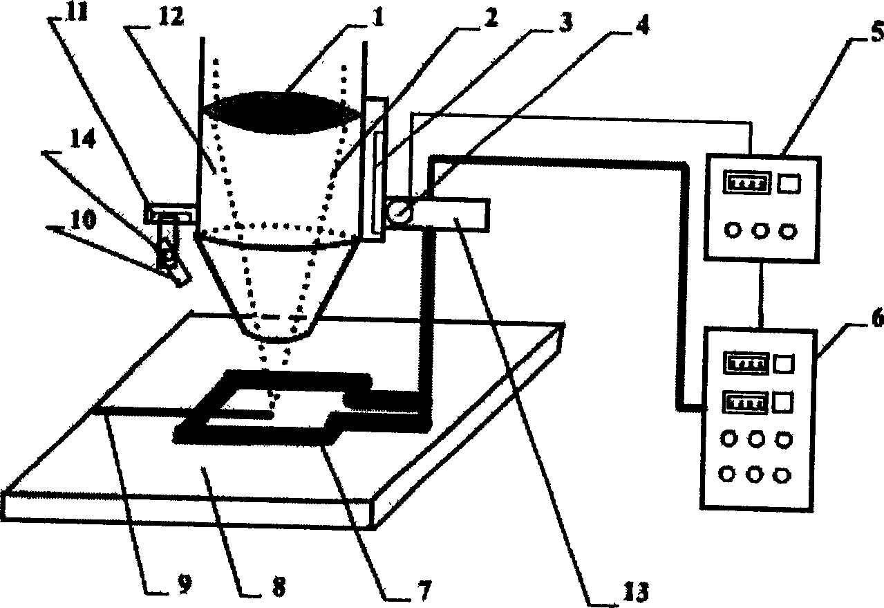
[0021] Option 1: If figure 1 As shown, the induction heating coil (7) and the laser beam (2) heat the workpiece welding area synchronously, and the focused laser beam (2) passes through the center of the induction heating coil and acts on the weld seam area to form deep penetration welding. The distance between the induction coil and the upper surface of the workpiece is 2mm, part of the energy of the induction heating coil directly heats the fusion zone to form the weld (9), and the other part is used to heat the surrounding area of ​​the weld (9). The angle between the infrared temperat...


PUM


Abstract

The present invention provides welder and welding method combining two different kinds of heat source, laser and HF inductor, and adopts real-time temperature monitor and control to overcome the demerits of common laser welding of metal material, which has low energy utilization and is likely to produce air hole. During welding, two kinds of heat source are used to heat the welded part and near part simultaneously. The welder of the present invention has laser welding head as the main body comprising integrated induction heating winding and infrared sensor. Compared with common laser welding, the present invention has greatly raised production efficiency and welding quality and can realize 2D and 3D welding.

Description

technical field [0001] The invention relates to a device and a welding method for welding by combining two heat sources of laser and high-frequency induction. Background technique [0002] Laser welding has the characteristics of high welding speed, large weld depth-to-width ratio, small heat-affected zone, small deformation, and easy automation. It has been widely used in industry, especially in the fields of automobile, metallurgy, aerospace and national defense. However, while laser welding technology is widely used, it also has certain limitations: many metal materials have high reflectivity, low absorption rate and low energy utilization rate for laser; the laser has a short action time on the base material, and the molten metal solidifies quickly. Fast, especially in high aspect ratio welds or non-penetrating welding, the metal vapor in the weld and the inhaled ambient gas are not easy to escape completely, resulting in the formation of pores or cavities; the heat inpu...

Claims


Application Information

Patent Timeline
Patent Type & Authority Applications(China)
IPC IPC(8): B23K13/01B23K26/346
Inventor 王春明胡席远刘建华胡伦骥陈俐
Owner HUAZHONG UNIV OF SCI & TECH
Why Eureka
Try Eureka