Traffic scheduling method and device, electronic equipment and storage medium

A flow scheduling and flow technology, applied in the field of network communication, can solve problems such as high server utilization, reduced service capacity, and low server performance

Pending Publication Date: 2020-12-29
HANGZHOU DPTECH TECH
9 Cites 0 Cited by

AI-Extracted Technical Summary

Problems solved by technology

However, these scheduling algorithms may lead to low performance of the scheduled servers themselves, or make the utilization ra...

Method used

As can be seen from the technical solution provided by the above application, when the load balancing device receives the flow sent by the client, according to the running status data of each server in the obtained physical server cluster, the priority of each server is determined, and the priority Scheduling the traffic to the best performing server in the physical server cluster. By considering the server's own performance and bringing the server's own operating data into the scheduling algorithm, the load balancing device avoids scheduling traffic to servers with poor performance during the process of scheduling traffic, t...

Abstract

The invention provides a traffic scheduling method and device, electronic equipment and a storage medium. The method can comprise the following steps: obtaining operation state data of each server ina physical server cluster corresponding to a virtual service; determining priorities respectively corresponding to the servers according to the running state data; and when the traffic for the virtualservice is received, preferentially scheduling the traffic to a server with a relatively higher priority in the physical server cluster. By means of the technical scheme, it can be guaranteed that the flow is scheduled to the server with the best performance, the situation that the flow is scheduled to the server with the poor running state is avoided, and the situation that normal transmission of the flow is affected due to the fact that the running load of part of servers is too large in the flow scheduling process is avoided.

Application Domain

Transmission

Technology Topic

EngineeringFlow scheduling +4

Image

  • Traffic scheduling method and device, electronic equipment and storage medium
  • Traffic scheduling method and device, electronic equipment and storage medium
  • Traffic scheduling method and device, electronic equipment and storage medium

Examples

  • Experimental program(1)

Example Embodiment

[0026] Reference will now be made in detail to the exemplary embodiments, examples of which are illustrated in the accompanying drawings. When the following description refers to the accompanying drawings, the same numerals in different drawings refer to the same or similar elements unless otherwise indicated. The implementations described in the following exemplary embodiments do not represent all implementations consistent with this application. Rather, they are merely examples of apparatuses and methods consistent with aspects of the present application as recited in the appended claims.
[0027] The terminology used in this application is for the purpose of describing particular embodiments only, and is not intended to limit the application. As used in this application and the appended claims, the singular forms "a", "the", and "the" are intended to include the plural forms as well, unless the context clearly dictates otherwise. It should also be understood that the term "and/or" as used herein refers to and includes any and all possible combinations of one or more of the associated listed items.
[0028] It should be understood that although the terms first, second, third, etc. may be used in this application to describe various information, the information should not be limited to these terms. These terms are only used to distinguish information of the same type from one another. For example, without departing from the scope of the present application, first information may also be called second information, and similarly, second information may also be called first information. Depending on the context, the word "if" as used herein may be interpreted as "at" or "when" or "in response to a determination."
[0029] Next, the embodiments of this specification will be described in detail.
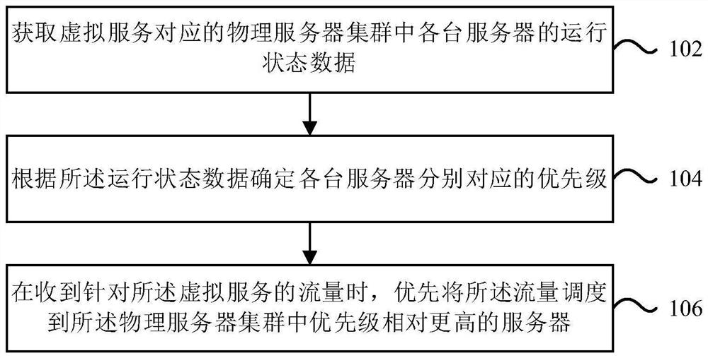
[0030] figure 1 It is a flowchart of a traffic scheduling method according to an exemplary embodiment of the present application. like figure 1 As shown, the method is applied to a load balancing device, and may include the following steps:
[0031] Step 102: Obtain the running status data of each server in the physical server cluster corresponding to the virtual service.
[0032] The running status data may include the performance data of each server, or monitor the data transmission status information of the network link between the load balancing device and each server, or monitor the performance data of each server and monitor the load balancing device and each server. Data transmission status information of network links between servers.
[0033] In an embodiment, the performance data of the server may include server CPU usage, server memory usage, etc. In fact, all parameter values ​​that can be used to characterize server performance can be applied here, and this application does not limit this; The data transmission state information of the network link between the balancing device and each server may be the network delay time between the load balancing device and each server.
[0034] Among them, the CPU and memory usage of each server in the physical server cluster can be obtained by the load balancing device in real time according to SNMP (Simple Network Management Protocol, Simple Network Management Protocol); the network delay between the load balancing device and the server can be determined by The load balancing device obtains the information according to ICMP (Internet ControlMessage Protocol, control message protocol).
[0035] Step 104: Determine the respective priorities of each server according to the running status data.
[0036] Through the preset running status priority algorithm, the priority value of each server is calculated according to the running status data of each server and the weight configured for each running status data in advance.
[0037] The pre-configured weights for each item of running status data may be individualized weights configured for each server, or a unified weight set for all servers in the physical server cluster.
[0038] Because each running status data in servers with different hardware configurations has different impacts on the performance of the server itself, if the same weight is configured for each server, the calculated priority may be unreasonable. In order to better calculate the priority of each server, the personalized weight of each server configuration can be preferentially selected during calculation.
[0039] In this embodiment, it is judged whether each server is configured with a personalized weight, and if yes, the corresponding priority of each server is calculated according to the running status data and the personalized weight configured by each server; if not, according to the running The status data and the unified weight set by all servers in the physical server cluster calculate the priority corresponding to each server.
[0040] For ease of understanding, the following is a simple example of the running status priority algorithm:
[0041] The running state priority algorithm can be Among them, A is the priority value of the running status, C is the usage rate of the server CPU, X is the weight of the server CPU, M is the usage rate of the server memory, Y is the weight of the server memory, T is the delay time, and S is the average delay time of the server.
[0042] The running state priority value calculated according to this running state priority algorithm formula is normally related to CPU usage, memory usage, and delay time. According to the common knowledge of those skilled in the art, the larger the values ​​of the CPU usage, the memory usage, and the delay time, the worse the performance of the server.
[0043] Therefore, the larger the running state priority value obtained according to the above running state priority algorithm, the lower the priority, and the smaller the running state priority value, the higher the priority.
[0044] If it is calculated according to the running state data that at least two servers have the same priority, then acquiring load data of the at least two servers, and determining the priority of the at least two servers according to the load data.
[0045] The load data may include incoming traffic, outgoing traffic, number of concurrent sessions, number of new sessions, etc. of the server. In fact, all parameter values ​​that can be used to characterize the server load can be applied here, and this application does not limit this.
[0046] In this embodiment, the priority values ​​of the at least two servers are calculated according to the load data of the at least two servers and the pre-configured weights for each item of load data through a pre-designed load priority algorithm.
[0047] Specifically, determine whether the at least two servers are configured with personalized weights, and if so, calculate the respective priorities of the at least two servers according to the load data and the personalized weights configured by the at least two servers; If not, calculate the respective priorities corresponding to the at least two servers according to the load data and the uniform weights set by all the servers in the physical server cluster.
[0048]Similar to the running status priority algorithm, the preset load priority algorithm can be B=D*V+E*W, where B is the load priority value, D is the incoming traffic of the server, and E is the number of concurrent sessions, V is the weight of incoming server traffic, and W is the weight of concurrent sessions.
[0049] The load priority value calculated according to this load priority algorithm formula is normally related to the server's inflow traffic, outflow traffic, concurrent sessions, and new session numbers. According to the common knowledge of those skilled in the art, the larger the inflow traffic, the outflow traffic, the number of concurrent sessions, and the number of newly created sessions of the server, the higher the server load and the worse the performance.
[0050] Therefore, the larger the value of the load priority obtained according to the above load priority algorithm, the lower the priority, and the smaller the value of the load priority, the higher the priority.
[0051] If it is calculated according to the load data that at least two servers have the same priority, then obtain the predefined order of arrangement of the at least two servers in the physical server cluster, and determine that the server arranged first corresponds to a relatively higher priority.
[0052] In another embodiment of the present application, step 104 determines the corresponding priority of each server according to the running status data, or directly adds the obtained running status parameters, and the sum of the running status parameter values The smaller the priority, the greater the sum of the running state parameter values, the smaller the priority.
[0053] Step 106: When receiving traffic for the virtual service, preferentially dispatch the traffic to a server with a relatively higher priority in the physical server cluster.
[0054] It can be seen from the above technical solution provided by this application that when the load balancing device receives the traffic sent by the client, it determines the priority of each server according to the obtained running status data of each server in the physical server cluster, and prioritizes the Traffic is dispatched to the best performing server in the physical server cluster. By considering the server's own performance and bringing the server's own operating data into the scheduling algorithm, the load balancing device avoids scheduling traffic to servers with poor performance during the process of scheduling traffic, thereby providing better network services.
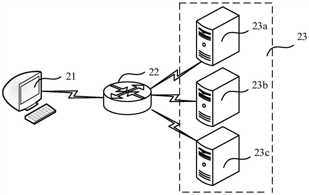
[0055] figure 2 As shown, it is a schematic diagram of the network architecture of the traffic scheduling system applying the embodiment of the present application. like figure 2 As shown, the traffic scheduling system may include a client 21 , a load balancing device 22 and a server cluster 23 , and the load balancing device 22 implements traffic scheduling between the client 21 and the server cluster 23 . Wherein, the server cluster 23 includes multiple servers, such as figure 2 The server 23a, the server 23b, and the server 23c are shown. Of course, the present application does not limit the number of servers included in the server cluster 23 . The above-mentioned servers 23 a - 23 c can provide the same service, so that the load balancing device 22 can arbitrarily distribute the traffic from the client 21 to a certain server, all of which can meet the service requirements of the client 21 . The load balancing device 22 needs to select a server from the server cluster 23 to distribute the traffic from the client 21 to the selected server. Similarly, when the load balancing device 22 also receives traffic sent by other clients, it A server is selected from the server cluster 23 to distribute the received traffic to the selected server, thereby achieving load balancing among the servers.
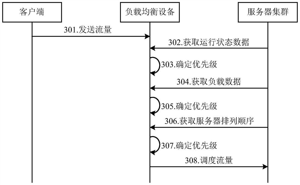
[0056] In the technical solution of the present application, by improving the selection process of the server by the load balancing device 22, the optimization of the above-mentioned load balancing can be realized, combined below image 3 Describe in detail. in, image 3 According to an exemplary embodiment of the present application, a flow chart of multi-party interaction of a traffic scheduling method is shown. like image 3 As shown, the interaction process between the client 21, the load balancing device 22, and the server cluster 23 includes the following steps:
[0057] Step 301 , the client 21 sends traffic to the load balancing device 22 .
[0058] Step 302 , the load balancing device 22 acquires the running status data of each server in the server cluster 23 .
[0059] The running status data of the servers may include the performance data of each server or the data transmission status information of the network link between the load balancing device and each server, or the performance data of each server and the relationship between the load balancing device and each server. Data transfer status information for network links between servers. Specifically, the performance data of the server may include server CPU usage, server memory usage, etc. In fact, all parameter values ​​that can be used to characterize server performance can be applied here, and this application does not limit this; the load balancing device and The data transmission status information of the network links between the servers may be the network delay time between the load balancing device and the servers.
[0060] For example, the running status data of each server in the server cluster is shown in Table 1:
[0061] CPU usage memory usage Delay time/ms server 1 60% 25% 8 server 2 40% 60% 8 server 3 20% 30% 15 server 4 10% 50% 13 server 5 50% 60% 6
[0062] Table 1
[0063] In step 303, the load balancing device 22 determines the priority of each server according to the obtained running status data.
[0064] For example, the set weights are shown in Table 2:
[0065]
[0066]
[0067] Table 2
[0068] Set the running state priority algorithm to Among them, A is the priority value of the running status, C is the usage rate of the server CPU, X is the weight of the server CPU, M is the usage rate of the server memory, Y is the weight of the server memory, T is the delay time, and S is the average delay time of the server.
[0069] S=(8+8+15+13+6)/5=10
[0070] A 1 =0.6*0.4+0.25*0.4+(8/10)*0.2=0.5
[0071] A 2 =0.4*0.4+0.5*0.4+(8/10)*0.2=0.52
[0072] A 3 =0.2*0.4+0.3*0.4+(15/10)*0.2=0.5
[0073] A 4 =0.1*0.4+0.5*0.4+(13/10)*0.2=0.5
[0074] A 5 =0.5*0.4+0.6*0.4+(6/10)*0.2=0.56
[0075] The larger the running state priority value obtained according to the above running state priority algorithm, the lower the priority, and the smaller the running state priority value, the higher the priority.
[0076] Therefore, the priority ranking of each server in the server cluster is: server 1 = server 3 = server 4 > server 2 > server 5 .
[0077] If the server with the highest priority can be distinguished according to the running state data in step 303 , it may directly jump from step 303 to step 308 instead of going to step 304 .
[0078] Step 304: the load balancing device 22 obtains the load data of each server in the physical server cluster.
[0079] When the priorities of the at least two servers calculated according to the running status data are the same, acquiring load data of the at least two servers, and determining the priorities of the at least two servers according to the load data.
[0080] In this embodiment, it is calculated according to the running state data that the servers 1, 3, and 4 have the same priority, and the load balancing device acquires the load data of the servers 1, 3, and 4.
[0081] The load data may include incoming traffic, outgoing traffic, number of concurrent sessions, number of new sessions, etc. of the server. In fact, all parameter values ​​that can be used to characterize the server load can be applied here, and this application does not limit this.
[0082] Step 305: The load balancing device 22 determines the priorities of the at least two servers according to the load data.
[0083] In this embodiment, through the pre-designed load priority algorithm, the at least two The priority value of the server.
[0084] For example, the preset load priority algorithm is B=D*V+E*W, where B is the value of the load priority, D is the incoming traffic of the server, E is the number of concurrent sessions, and V is the weight of the incoming traffic of the server. W is the weight of session concurrency.
[0085] The load data of servers 1, 3, and 4 in the server cluster and the personalized weights of the configured load data are shown in Table 3:
[0086] inflow traffic concurrent sessions Incoming traffic weight Session Concurrency Weight server 1 12 8 0.4 0.6 server 3 7.2 12 0.5 0.5 server 4 20 4 0.4 0.6
[0087] table 3
[0088] B 1 =12*0.4+8*0.6=9.6
[0089] B 3 =7.2*0.5+12*0.5=9.6
[0090] B 4 =20*0.4+4*0.6=10.4
[0091] The greater the value of the load priority obtained according to the above load priority algorithm, the lower the priority, and the smaller the value of the load priority, the higher the priority.
[0092] Therefore, the priority ranking of each server in the server cluster is: server 1 = server 3 > server 4 > server 2 > server 5 .
[0093] If the server with the highest priority can be distinguished according to the load data in step 305, it may directly jump from step 305 to step 308 instead of going to step 306.
[0094] Step 306: The load balancing device 22 obtains the arrangement order of the servers in the physical server cluster.
[0095] Step 307: The load balancing device 22 determines the server priority according to the arrangement order of the servers.
[0096] When the priorities of at least two servers calculated according to the load data are the same, then obtain the predefined arrangement order of the at least two servers in the physical server cluster, and determine that the server arranged first corresponds to a relatively higher priority.
[0097] In this embodiment, server 1 and server 3 have the same priority, and according to the predefined order of the two servers in the physical server cluster, it is determined that server 1 has a higher priority than server 3 .
[0098]To sum up, the priorities of the servers in the server cluster are: server 1 > server 3 > server 4 > server 2 > server 5 .
[0099] Step 308 , the load balancing device 22 dispatches the traffic sent by the client 21 to the server with the highest priority in the server cluster 23 .
[0100] According to the priority ranking of each server in the server cluster in the above example, when the load balancing device receives traffic from the client, it will prioritize the traffic to server 1.
[0101] Corresponding to the foregoing method embodiments, this specification also provides an apparatus embodiment.
[0102] Figure 4 It is a schematic diagram of a traffic scheduling electronic device according to an exemplary embodiment of the present application. refer to Figure 4 , at the hardware level, the electronic device includes a processor 402, an internal bus 404, a network interface 406, a memory 408, and a non-volatile memory 410, and of course may include hardware required by other services. The processor 402 reads the corresponding computer program from the non-volatile memory 410 into the memory 408 and then runs it, forming a device for solving the problem of dual-machine hot backup and dual-master on a logical level. Of course, in addition to the software implementation, this application does not exclude other implementations, such as logic devices or the combination of software and hardware, etc., that is to say, the execution subject of the following processing flow is not limited to each logic unit, and can also be hardware or logic device.
[0103] Figure 5 It is a block diagram of a flow scheduling device according to an exemplary embodiment of the present application. refer to Figure 5 , the device includes an acquisition unit 502, a first determination unit 504, and a scheduling unit 506, wherein:
[0104] The acquiring unit 502 is configured to acquire the running status data of each server in the physical server cluster corresponding to the virtual service.
[0105] The first determining unit 504 is configured to determine the respective priorities of the servers according to the running status data.
[0106] The scheduling unit 506 is configured to, when receiving traffic for the virtual service, preferentially dispatch the traffic to a server with a relatively higher priority in the physical server cluster.
[0107] Optionally, the running status data specifically includes performance data of each server, and/or data transmission status information for monitoring network links between the load balancing device and each server.
[0108] Optionally, the performance data includes: server CPU usage and/or server memory usage; the data transmission status information includes: data transmission delay time of the network link between the load balancing device and the server.
[0109] Optionally, the first determining unit 504 is specifically configured to: calculate the priority value of each server according to the running status data of each server and the weights configured in advance for each running status data.
[0110] Optionally, the pre-configured weights for each item of running state data include individualized weights configured for each server, or a unified weight set for all servers in the physical server cluster.
[0111] Optionally, the above-mentioned device also includes:
[0112] The second determination unit 508 is configured to obtain load data of the at least two servers when the priorities of at least two servers calculated according to the running status data are the same, and determine the Priority of at least two servers.
[0113] The load data may include the server's incoming traffic, outgoing traffic, number of concurrent sessions, number of new sessions, etc. In fact, all parameter values ​​that can be used to characterize the server load can be applied here, and this application does not limit this
[0114] Optionally, the above-mentioned device also includes:
[0115] The third determining unit 510 is configured to obtain a predefined arrangement order of the at least two servers in the physical server cluster in the case that the priorities of the at least two servers calculated according to the load data are the same, and determine Servers ranked first correspond to relatively higher priorities.
[0116] For the implementation process of the functions and effects of each unit in the above device, please refer to the implementation process of the corresponding steps in the above method for details, and will not be repeated here.
[0117] As for the device embodiment, since it basically corresponds to the method embodiment, for related parts, please refer to the part description of the method embodiment. The device embodiments described above are only illustrative, and the units described as separate components may or may not be physically separated, and the components shown as units may or may not be physical units, that is, they may be located in One place, or it can be distributed to multiple network elements. Part or all of the modules can be selected according to actual needs to achieve the purpose of the solution of this application. It can be understood and implemented by those skilled in the art without creative effort.
[0118] In an exemplary embodiment, there is also provided a non-transitory computer-readable storage medium including instructions, for example, a memory including instructions, the above instructions can be executed by a processor of the flow scheduling device to implement any of the above-mentioned embodiments. The method described above, for example, the method may include:
[0119] Obtain the running status data of each server in the physical server cluster corresponding to the virtual service; determine the corresponding priority of each server according to the running status data; when receiving the traffic for the virtual service, prioritize the traffic Scheduling to a server with a relatively higher priority in the physical server cluster.
[0120] Wherein, the non-transitory computer-readable storage medium may be ROM, random access memory (RAM), CD-ROM, magnetic tape, floppy disk, optical data storage device, etc., and the present application is not limited thereto.
[0121] The above is only a preferred embodiment of the application, and is not intended to limit the application. Any modifications, equivalent replacements, improvements, etc. made within the spirit and principles of the application should be included in the application. within the scope of protection.

PUM

no PUM

Description & Claims & Application Information

We can also present the details of the Description, Claims and Application information to help users get a comprehensive understanding of the technical details of the patent, such as background art, summary of invention, brief description of drawings, description of embodiments, and other original content. On the other hand, users can also determine the specific scope of protection of the technology through the list of claims; as well as understand the changes in the life cycle of the technology with the presentation of the patent timeline. Login to view more.
Why Eureka
Try Eureka