Valve device

A technology of valve device and cam device, which is applied in the direction of valve device, valve operation/release device, valve lift, etc. It can solve the problems of large opening torque, unbalanced valve body pressure, unsuitable sealing, etc.

Inactive Publication Date: 2003-09-17
OKANO VALVE MFG
View PDF2 Cites 2 Cited by
  • Summary
  • Abstract
  • Description
  • Claims
  • Application Information

AI Technical Summary

Problems solved by technology

[0004] In addition, in the inclined butterfly valve, although the design should only be the place where the contact between the valve body and the valve seat is fully closed, in fact, due to the looseness of the matching part of the rotary shaft of the above-mentioned valve body, a so-called gap is generated. When the valve is opened, the valve body and the valve seat mus...

Method used


Image

  • Valve device
  • Valve device
  • Valve device

Examples


Embodiment Construction

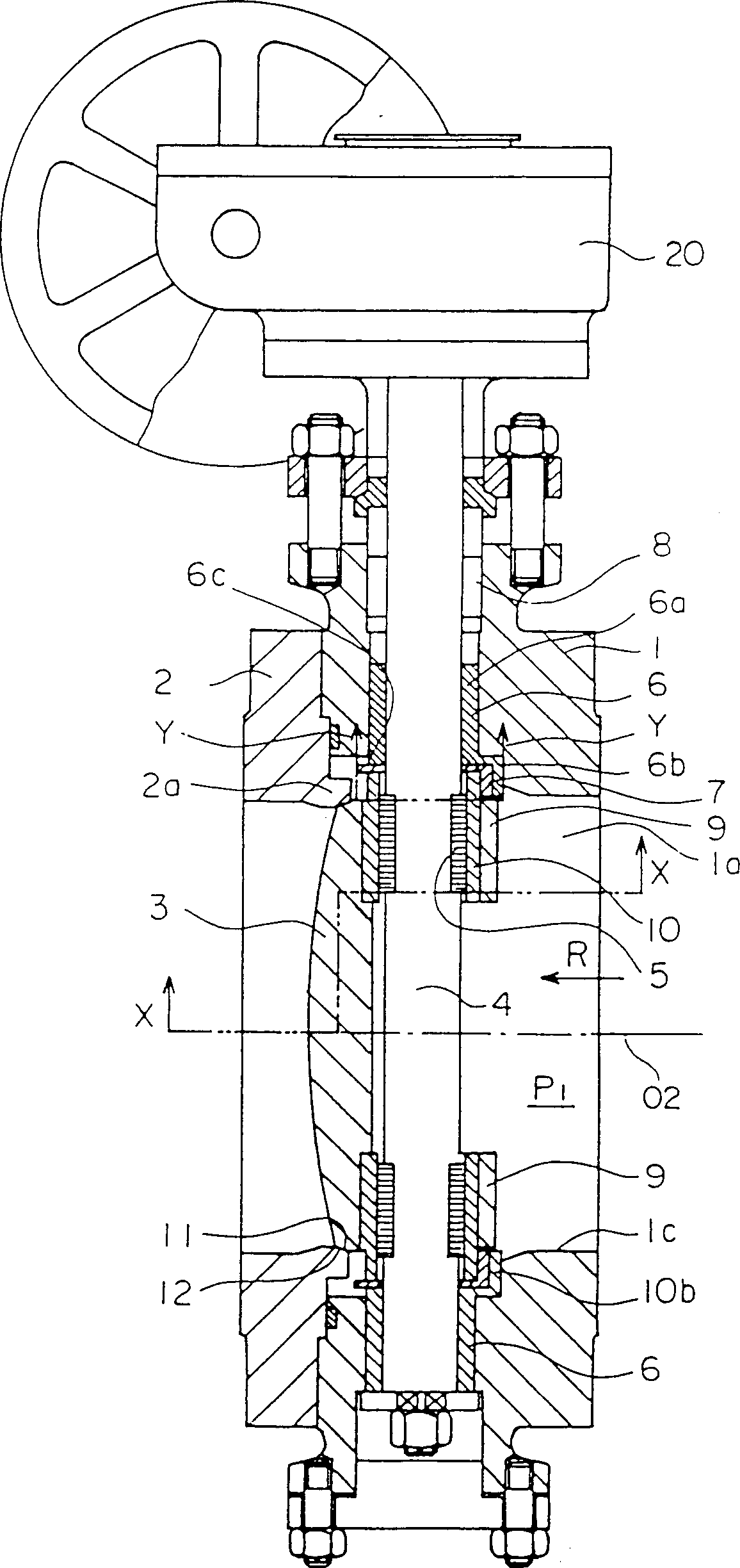
[0026] The preferred embodiment of the present invention will be described in detail below with reference to the accompanying drawings, in which the same symbols indicate the same or corresponding parts. In the following description, as far as the direction is concerned, the figure 1 The right side of the paper is the "front side", the left side of the paper is the "back side", and, in figure 1 Among them, the upper side of the central axis 02 is the "upper side" and the lower side is the "lower side". figure 1 The front side of the paper is the "left side", and the back side of the paper is the "right side".

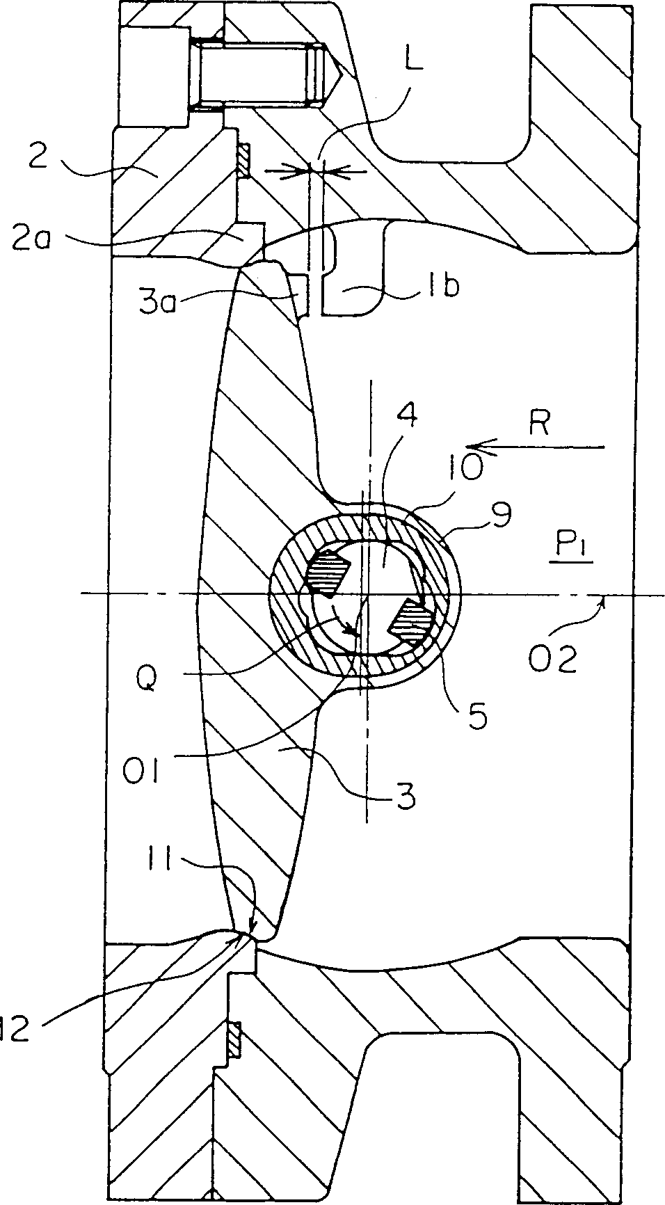
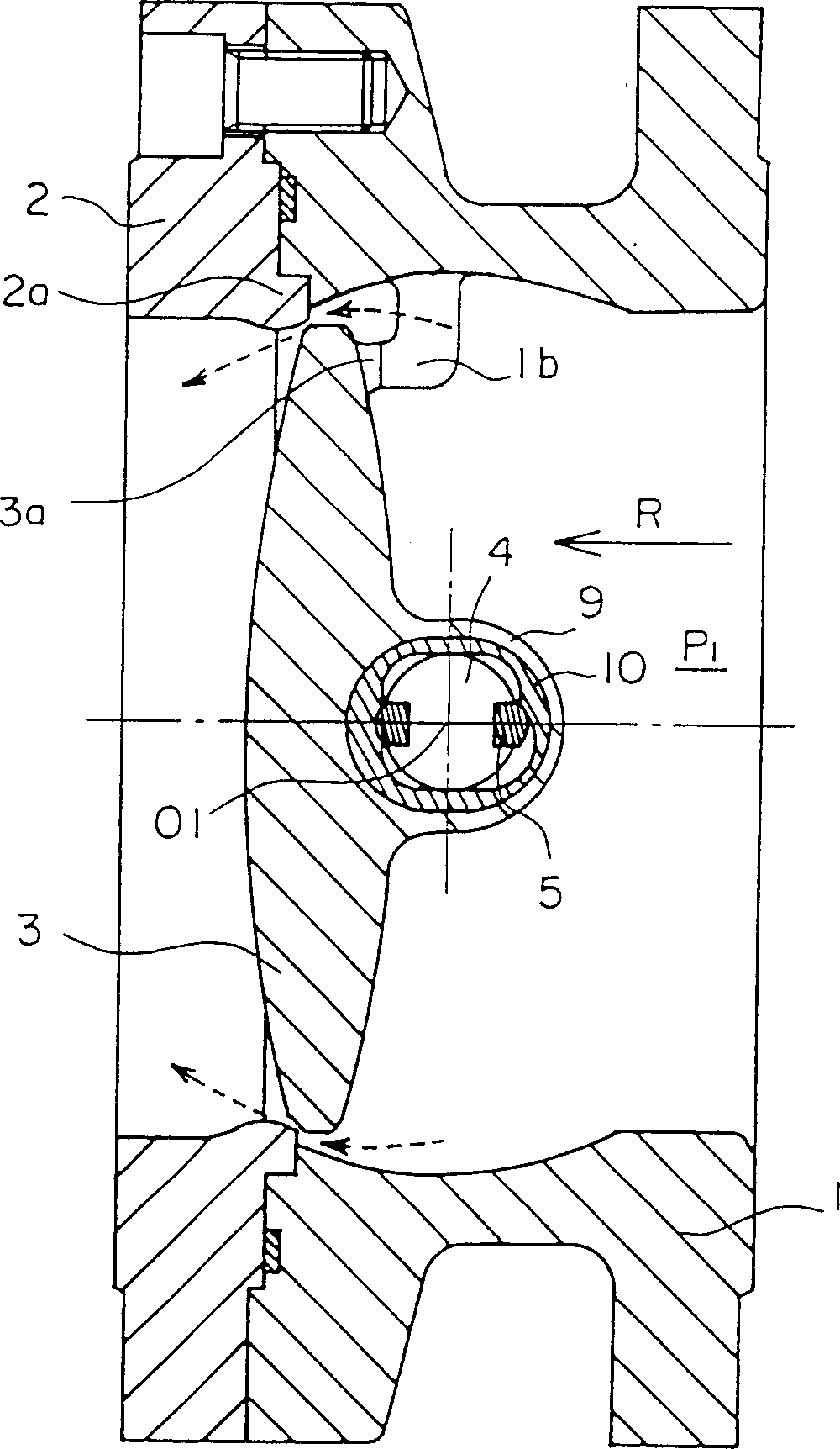
[0027] figure 1 It is a longitudinal sectional view of the valve device of this embodiment in a fully closed state. figure 2 for along figure 1 The cross-sectional view of the x-x line, image 3 and Figure 4 In order to respectively show the state in the middle of opening the valve and the state of full opening and figure 2 Quite a graph. The valve device of ...


PUM


Abstract

PROBLEM TO BE SOLVED: To keep the seal durability of a valve seat without any difficult work of excellent accuracy in machining the valve seat, and to reduce the operation force in opening a valve. SOLUTION: In a this valve device, a disk bush 10 to be integratedly connected to a boss part is arranged between a slide key 5 provided in a rod 4 and a boss part 9 of a valve element 3. A washer 7 is arranged around the disk bush 10, and the disk bush 10 and the washer 7 form a cylindrical assembly when they are closely fitted to each other. A bush 6 having a notch 6c in which the disk bush 10 can be locally projected on a seat ring 2a side is arranged around the washer 7. While the disk bush 10 is projected from the notch, the valve element 3 is moved straight. While the disk bush is retracted from the notch, the cylindrical assembly is turnably supported by the bush 6, and the valve element 3 is turned together with the rod 4.

Description

technical field [0001] The present invention relates to a valve device such as a butterfly valve, and in particular, to an improved valve device which aims at improving the sealing durability and reducing the operating force when opening the valve. Background technique [0002] Conventional butterfly valves generally use rubber on the valve seat, and such butterfly valves are generally not suitable for flow passages through which high-temperature and high-pressure fluids flow. Therefore, in butterfly valves used under high temperature and high pressure conditions, valve seats made of metal are used. As a butterfly valve having a metal seat, there is known a so-called inclined type valve, which uses a metal O-ring as a sealing material in the seat portion, and since the rotary shaft of the valve body is eccentric to the central axis of the fluid passage, in In the closed state of the valve, sealing pressure is applied to the inclined seat surface to maintain airtightness. ...

Claims


Application Information

Patent Timeline
IPC IPC(8): F16K1/22F16K1/226F16K1/24F16K1/32
CPCF16K1/2007F16K1/42F16K31/524
Inventor 冈野正敏吉富昭三喜田义胜坪井直武那须利胜井本幸夫
Owner OKANO VALVE MFG
Why Eureka
Try Eureka