
A liquid rocket engine pump screw wheel set bearing cooling structure

A liquid rocket and cooling structure technology, which is applied to rocket engine devices, bearing cooling, machines/engines, etc., can solve the problems of loss of high-pressure medium energy, increase of engine weight, and difficulty in product processing, so as to reduce fluid energy loss and reduce weight , the effect of simple structure

Active Publication Date: 2021-11-16
XIAN AEROSPACE PROPULSION INST
View PDF6 Cites 0 Cited by
  • Summary
  • Abstract
  • Description
  • Claims
  • Application Information

AI Technical Summary

Problems solved by technology

[0003] The bearing of the turbopump of liquid rocket engine is located in the pump chamber, and generally uses its own propellant for cooling. The usual method is: in addition to the main flow of propellant, an auxiliary flow path is specially set up to lead out from the area with higher pressure in the pump chamber. A high-pressure medium returns to the pump main circuit after cooling the bearings. This cooling method not only loses the energy of the high-pressure medium, but also reduces the efficiency of the pump.
In addition, more importantly, the auxiliary flow path in the pump is usually very complicated. Generally, the internal drainage will cause difficulties in product processing. In most cases, the corresponding pipeline is added outside the pump casing. The disadvantage is that the structure is complicated and the engine weight

Method used


Image

  • A liquid rocket engine pump screw wheel set bearing cooling structure
  • A liquid rocket engine pump screw wheel set bearing cooling structure
  • A liquid rocket engine pump screw wheel set bearing cooling structure

Examples


Embodiment Construction

[0041]The present invention will be further described in detail below in conjunction with the accompanying drawings and specific embodiments.

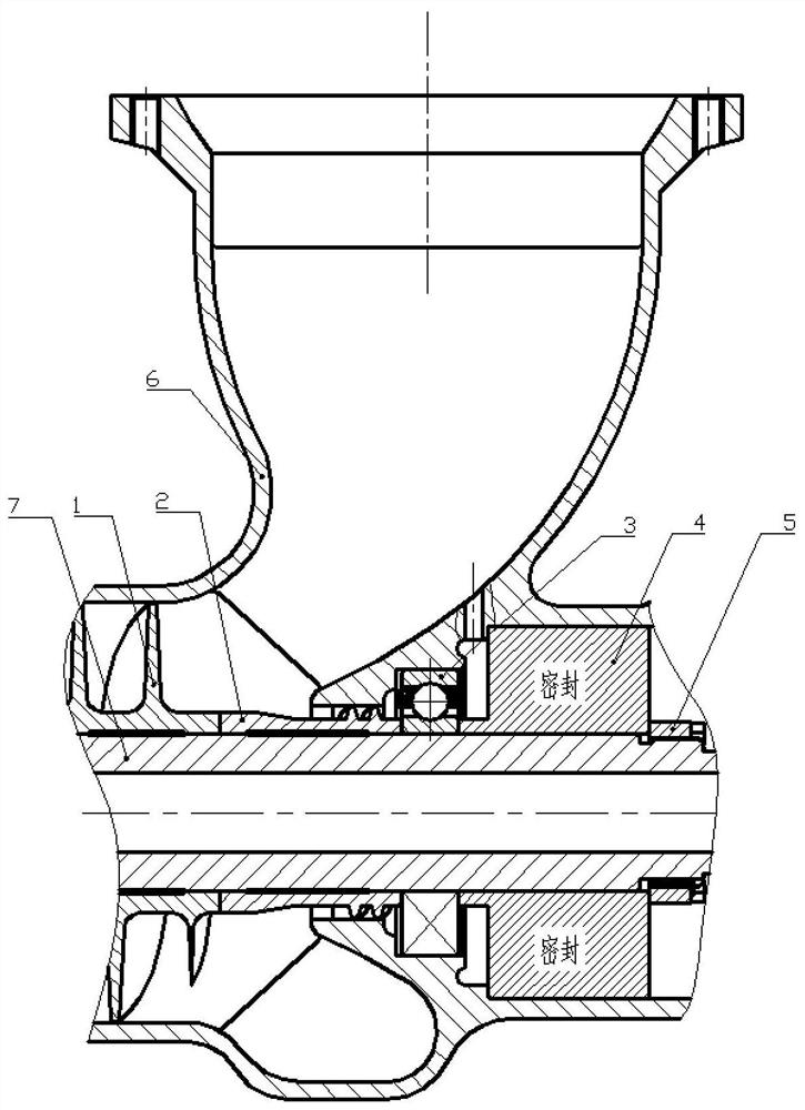
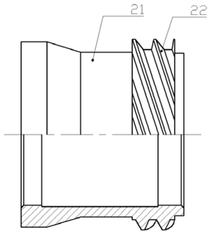
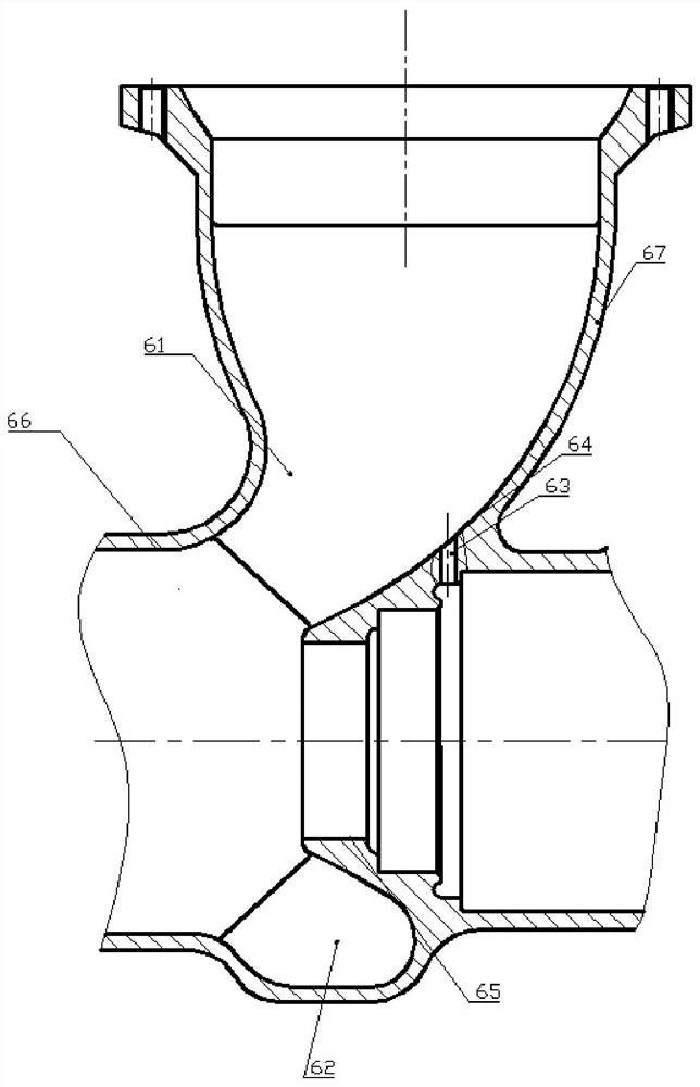
[0042] The invention relates to a liquid rocket engine pump spiral wheel pair bearing cooling structure, comprising: an induction wheel (1), a spiral wheel (2), a bearing (3), a seal (4), a shaft end compression nut (5), an inlet Housing (6) and shaft (7); inlet housing (6), including: inlet section (67) and ring section (68); ring section (68), including: outlet section, transition section and bearing cooling section; The inner cavity of the transition section of the annular section (68) is provided with a through hole (63) on the side close to the cooling section of the bearing; the liquid medium enters the inlet housing (6) from the inlet section (67) and flows out from the outlet section. , the shaft (7) drives the helical wheel (2) to rotate, generating a suction force, pumping part of the liquid medium passing through the transit...


PUM


Abstract

The invention relates to a liquid rocket engine pump spiral wheel pair bearing cooling structure, comprising: an induction wheel (1), a spiral wheel (2), a bearing (3), a seal (4), a shaft end compression nut (5), an inlet Housing (6) and shaft (7); inlet housing (6), including: inlet section (67) and ring section (68); ring section (68), including: outlet section, transition section and bearing cooling section; The inner cavity of the transition section of the annular section (68) is provided with a through hole (63) on the side close to the cooling section of the bearing; the liquid medium enters the inlet housing (6) from the inlet section (67) and flows out from the outlet section. , the shaft (7) drives the helical wheel (2) to rotate, generating a suction force, pumping part of the liquid medium passing through the transition section into the through hole (63) in the inner cavity of the transition section, flowing through the bearing (3) and then passing through, The spiral wheel (2) flows back to the transition section and merges into the outlet to cool the bearing. The invention simplifies the bearing cooling structure of the turbo pump of the engine and improves the pump efficiency while ensuring the cooling flow rate of the bearing.

Description

technical field [0001] The invention relates to a liquid rocket engine pump spiral wheel pair bearing cooling structure, which belongs to the technical field of liquid rocket engine turbine pump cooling. Background technique [0002] The turbopump of liquid rocket engine has high speed and high pressure. The high-speed rotating friction of the bearing supporting the rotor of the turbopump will cause the temperature to rise. During the process from starting to shutting down the engine, the turbopump will generate large axial force and radial force, both of which are determined by Bearing bearing, in order to balance the large amount of frictional heat generated by the bearing in the working process, the bearing must be continuously cooled. [0003] The bearing of the turbopump of liquid rocket engine is located in the pump chamber, and generally uses its own propellant for cooling. The usual method is: in addition to the main flow of propellant, an auxiliary flow path is spec...

Claims


Application Information

Patent Timeline
Patent Type & Authority Patents(China)
IPC IPC(8): F02K9/64F02K9/46F02K9/60F16C37/00
CPCF02K9/46F02K9/60F02K9/64F16C37/00
Inventor 于晴王晓锋李惠敏毛凯张聃安康李雨濛
Owner XIAN AEROSPACE PROPULSION INST
Learn More