Integrated high temperature resistant aerosol spray pipe

A spray pipe and high-temperature-resistant technology, which is applied in the spray device for cleaning and dust removal, and in the field of cooling, can solve the problems of reduced service life, complex structure, inconvenient installation and use, etc., and achieves convenient installation and use, large adjustable range, and simple structure Effect

Inactive Publication Date: 2011-12-28
武钢集团有限公司
View PDF6 Cites 2 Cited by
  • Summary
  • Abstract
  • Description
  • Claims
  • Application Information

AI Technical Summary

Problems solved by technology

[0004] 1. Water spray pipe: the water nozzle is installed on the water spray pipe. The advantage of this spray pipe is that it is simple in structure and easy to install and use. However, compared with the aerosol spray pipe, its disadvantage is that the spray medium The uniformity of distribution is not good, and the atomization effect of water is poor, which leads to the cooling uniformity not as good as that of the aerosol spray pipe. In addition, because the nozzles used are water nozzles, the nozzles have small apertures and are easy to block
Due to the use of aerosol nozzles, the structure of the spray pipe has the advantages of good atomization effect, uniform distribution of the spray medium, large nozzle aperture and not easy to block, etc., but its structure is complex, especially in a closed environment, it is inconvenient to install and use
[0006] 3. Closed box-type spray pipe: This kind of spray pipe is equipped with a metal box outside the above-mentioned aerosol spray pipe for protection, but this structure cannot be used in high temperature environments, otherwise the external box will It will be deformed due to high temperature, reduce the service life, and even cannot be used normally

Method used


Image

  • Integrated high temperature resistant aerosol spray pipe
  • Integrated high temperature resistant aerosol spray pipe
  • Integrated high temperature resistant aerosol spray pipe

Examples


Embodiment Construction

[0029] Below in conjunction with embodiment and attached Figure 1-2 The present invention is described further, but the present invention is not limited.

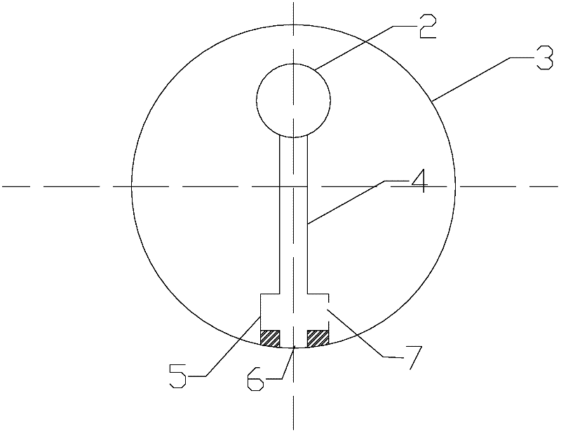
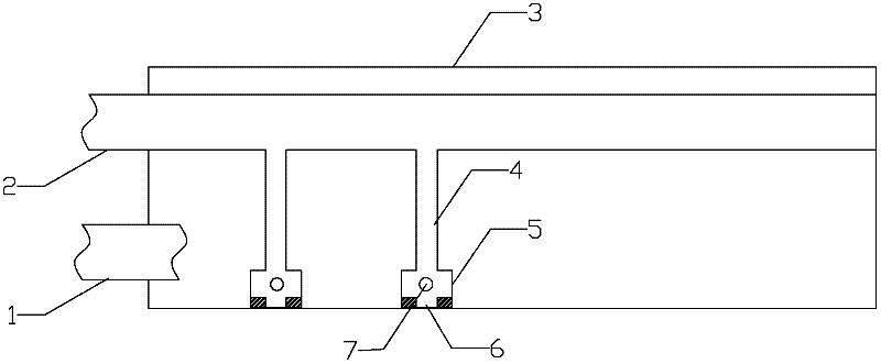
[0030] One-piece high-temperature-resistant aerosol spray pipe, the air pipe 2 is installed inside the water pipe 3 of the spray pipe, and then connected to the air-water mixing chamber 5 through the branch pipe 4, the gas enters the air-water mixing chamber 5 through the air pipe 2 and the branch pipe 4, and after mixing with water Spray outwards through an aerosol nozzle (not shown);

[0031] Water enters the spray pipe through the external water pipe 1 and fills the entire spray pipe water pipe 3. Under the action of pressure, it enters the air-water mixing chamber 5 through the water inlet hole 7, and finally sprays outward through the aerosol nozzle (not shown);

[0032] The outer wall of the spray pipe, that is, the water pipe 3 of the spray pipe, is self-cooled by the cooling water in the pipe to achieve the purpos...


PUM


Abstract

The invention relates to an integrated high-temperature-resistant aerosol spray pipe, which belongs to the technical field of cooling and dust removal, and includes an air pipe, a spray pipe water pipe, an air-water mixing chamber and an aerosol nozzle connected to the mixing chamber, and is characterized in that: the air pipe and the spray pipe The water pipes are arranged parallelly in the water pipe of the spray pipe, the mixing chamber is arranged in the water pipe of the spray pipe, and both the air pipe and the water pipe of the spray pipe are connected with the mixing chamber. The air pipe of the present invention is installed inside the water pipe of the spray pipe, the external structure is simple, and the installation and use are convenient; the outer wall of the spray pipe is self-cooled by the cooling water in the pipe, and can be used under high temperature and closed conditions; the air-water mixing chamber of the aerosol nozzle is built-in For the spray pipe, the structure of the external nozzle is simple; the air mist cooling method is adopted, the cooling is uniform, and the cooling intensity can be adjusted in a large range.

Description

technical field [0001] The invention belongs to the technical field of cooling and dust removal, in particular to a spray device for cooling, cleaning and dust removal in the fields of metallurgy, chemical industry, environmental protection and the like. Background technique [0002] The spray pipe refers to the installation of nozzles of varying numbers on the tubular structure. The spray medium reaches the nozzle through the pipe and is sprayed outward from the nozzle to achieve the purpose of cooling, cleaning, dust removal, etc. It is widely used in metallurgy, chemical industry, environmental protection, cleaning and other industries. widely. [0003] Among the various sprinkler pipes currently in use, there are mainly the following three forms: [0004] 1. Water spray pipe: the water nozzle is installed on the water spray pipe. The advantage of this spray pipe is that it is simple in structure and easy to install and use. However, compared with the aerosol spray pipe,...

Claims


Application Information

Patent Timeline
Patent Type & Authority Applications(China)
IPC IPC(8): B05B7/04
Inventor 彭著刚骆忠汉曹同友曹阳高文芳吴杰张剑君杨治争
Owner 武钢集团有限公司
Why Eureka
Try Eureka