Motor

A motor and brush technology, applied in the field of motors, can solve problems such as obstacles and increase in the number of components, and achieve the effects of reducing costs, simplifying external structures, and reducing the number of components.

Inactive Publication Date: 2013-09-11
MITSUBA CORP
View PDF6 Cites 2 Cited by
  • Summary
  • Abstract
  • Description
  • Claims
  • Application Information

AI Technical Summary

Problems solved by technology

[0004] However, in the conventional case where bolts and nuts provided on the outside of the motor case are used to prevent the terminals from falling off, the external dimensions of the motor will increase accordingly due to the provision of bolts and nuts, so that when mounted on a vehicle, This part will become an obstacle, or the number of parts will increase accordingly due to the use of bolts and nuts

Method used


Image

  • Motor
  • Motor
  • Motor

Examples


Embodiment Construction

[0022] (motor)

[0023] Hereinafter, an embodiment of the present invention will be described with reference to the drawings.

[0024] The electric motor of this embodiment is used as a starter motor of an engine of a motorcycle. When using the electric motor of this embodiment, the rotating shaft is connected with the crankshaft of an engine.

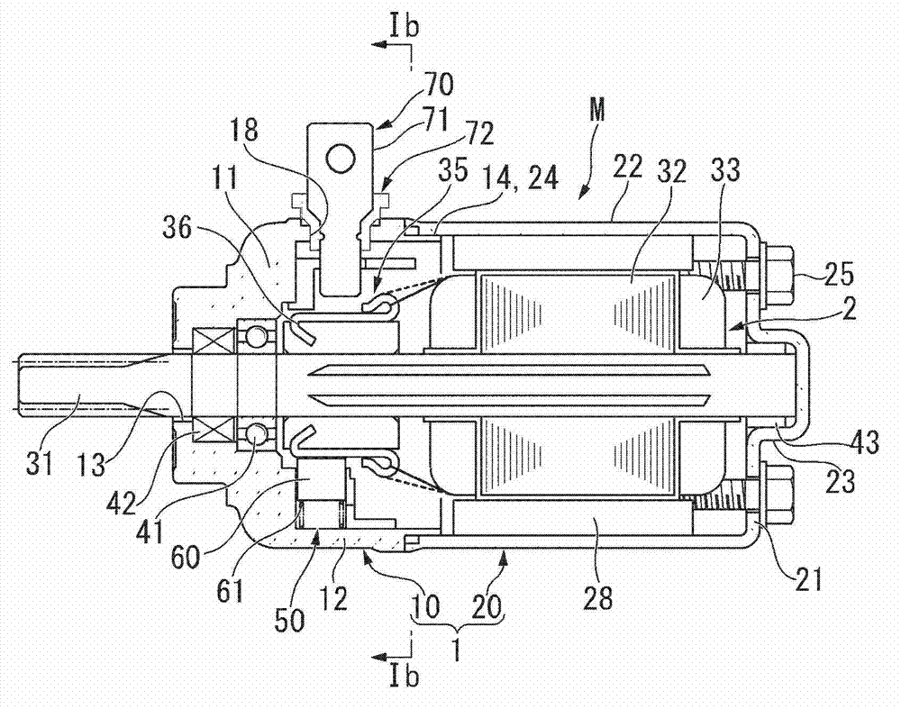
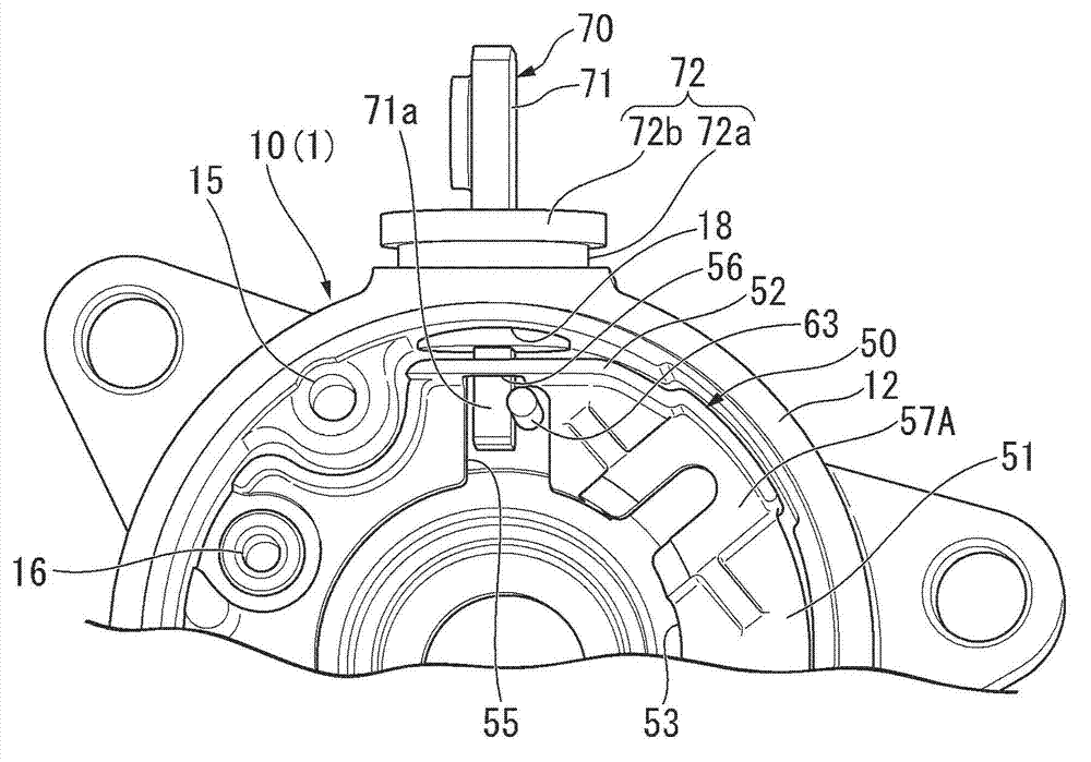
[0025] Such as figure 1 A and figure 1 As shown in B, the motor M includes: a motor casing 1 constituting a stator; a rotor 2 freely rotatably supported on the motor casing 1; The commutator 35 performs switching; the brush 60 makes current flow in the commutator 35 by slidingly contacting the commutator segment 36 of the commutator 35 ; and the terminal 71 supplies power to the brush 60 from the outside.

[0026] The motor case 1 is divided into a front case 10 having a front end wall 11 and a peripheral wall 12 , and a rear case 20 having a rear end wall 21 and a peripheral wall 22 . In addition, in the state where the rear end ...


PUM


Abstract

A motor comprises an electric brush and further comprises a terminal (71) inserted into a brush holder (50) through a through hole (18) of a circumferential wall (12) from the outside of a motor shell (1), a flexible braided wire (63) enabling the terminal (71) to be communicated with the electric brush, and the brush holder (50) fixed inside of the motor shell (1) and made of resin. A cutting groove (56) which is capable of accommodating the terminal (71) from one end side in the axial direction is formed on a circumferential wall (52) of the brush holder (50) at a position corresponding to the terminal (71). A gap, corresponding to the jointing part of the flexible braided wire (63) and the terminal (71), among gaps between the circumferential edge of the cutting groove (56) of the brush holder (50) and the terminal (71) is set to be smaller than the wire diameter of the flexible braided wire (63).

Description

technical field [0001] The present invention relates to an electric motor including a commutator (also referred to as a commutator or an element of a commutator) and brushes, for example, to an electric motor suitable for use as a starter motor of a two-wheeled vehicle. [0002] This application claims priority based on Japanese Patent Application No. 2012-040028 filed in Japan on February 27, 2012 and Japanese Patent Application No. 2013-007869 filed in Japan on January 18, 2013, and the contents thereof are cited into this application. Background technique [0003] In such a motor, there is a type in which a terminal for supplying power to the brushes from the outside is penetratingly provided on the peripheral wall of the motor case via an insulator. The existing electric motor includes the following structure: by using the bolts and nuts arranged outside the motor casing, the terminals penetrating the peripheral wall of the motor casing are firmly fixed on the motor cas...

Claims


Application Information

Patent Timeline
Patent Type & Authority Applications(China)
IPC IPC(8): H02K5/22H02K5/14
Inventor 上原修二樱井清崇宫崎崇行
Owner MITSUBA CORP
Why Eureka
Try Eureka