
A kind of gunpowder gas cooling device

A technology for cooling devices and gas, which is applied in the direction of household refrigeration devices, separation methods, lighting and heating equipment, etc. It can solve the problems of low cost performance, low cooling effect of cooling components, and inability of gas generators to meet actual use requirements, etc.

Active Publication Date: 2022-04-22
CHUANNAN MACHINERY PLANT CHINA ASTRONAUTIC SCI &TECH GROUP CORP
View PDF9 Cites 0 Cited by
  • Summary
  • Abstract
  • Description
  • Claims
  • Application Information

AI Technical Summary

Problems solved by technology

Its application fields are generally divided into two categories: one is the work type, and the other is the inflatable type; the work type gas generator generally does not have strict requirements on the gas outlet temperature, but with the wide application of composite materials and the consistency of work It is also hoped that there will be clean and low-temperature gas to do work; and inflatable gas generators are limited by the external environment such as airbag materials, the gas outlet temperature will be limited below 500 ° C, and solid residues in the gas are not allowed, traditional The existing gas generators can no longer meet the actual use requirements, and relevant units have also carried out related research, but there are the following problems:
[0003] 1) The cooling components account for a large proportion, and the cost performance is not high;
[0004] 2) The cooling components are not modularized;
[0005] 3) The cooling effect of the cooling component is not great, and the output gas temperature is too high
[0006] Therefore, the traditional gas generator can realize basic functions functionally, but has no advantages in gas temperature control, gas cleanliness control, space utilization and modularization.

Method used


Image

  • A kind of gunpowder gas cooling device
  • A kind of gunpowder gas cooling device
  • A kind of gunpowder gas cooling device

Examples


Embodiment Construction

[0050] The present invention will be further described in detail below in conjunction with the accompanying drawings and specific embodiments.

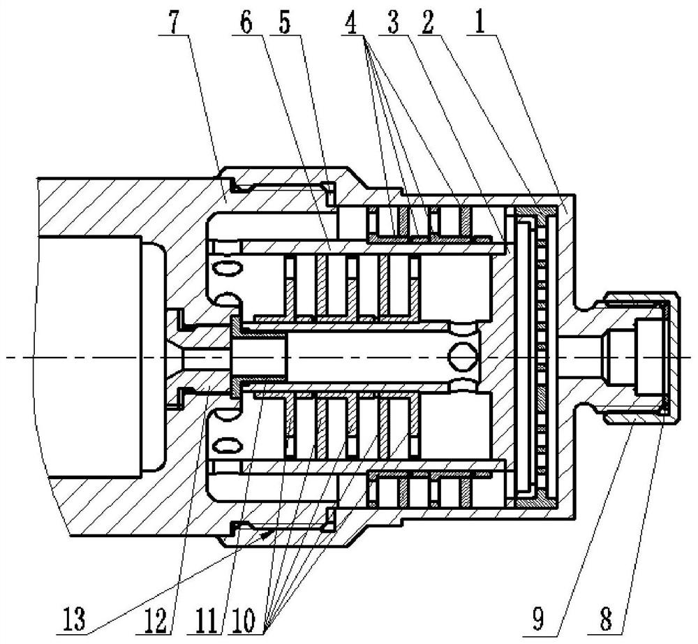
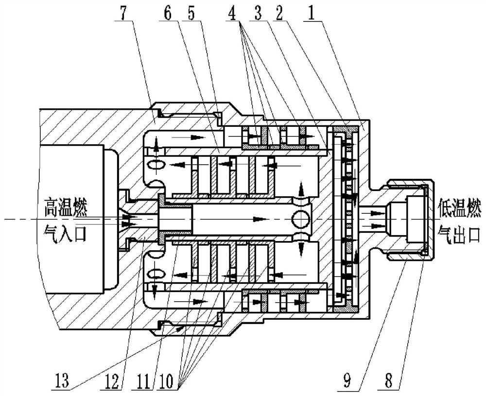
[0051] like figure 1 As shown, a propellant gas cooling device of the present invention includes: a blocking plate 11 , a primary cooling component, a secondary cooling component and a filter plate assembly 2 . The primary cooling component and the secondary cooling component divide the cooling device into multi-layer cavities radially from the inside to the outside, figure 2 As shown, the high-temperature gas is sprayed into the innermost cavity through the blocking plate 11, flows through the cavities of each layer in sequence from the inside to the outside, and then flows out through the filter plate assembly 2.

[0052] The flow direction of the high-temperature gas in the chambers of two adjacent layers is opposite; at the same time, the chamber is provided with multi-layer partitions arrayed along the axial direction, and thro...


PUM


Abstract

A propellant gas cooling device, comprising: a blocking plate, a primary cooling component, a secondary cooling component and a filter plate assembly. The primary cooling part and the secondary cooling part divide the cooling device into multi-layer cavities radially from inside to outside; high-temperature gas is sprayed into the innermost cavity through the blocking plate, and flows through each layer of cavities in turn from inside to outside After that, it flows out through the filter plate assembly; the flow direction of the high-temperature gas in the two adjacent layer chambers is opposite; at the same time, the chamber is provided with multi-layer partitions arrayed along the axial direction, and there are through holes in the circumferential direction of the partitions, and the gas on the two adjacent partitions The via locations are staggered. In the present invention, structural parts are added at the outlet of the gas, and the length of the structural parts is increased in series, and a multi-layer casing is formed by being set, so that the flow path of the gas is changed, the contact area between the gas and the structural parts and the passage stroke are increased, and the high-temperature gas and the structural parts are fully exchanged. Heat, using the temperature difference and thermal tolerance between the high-temperature gas and the cooling structure whose proportion is not larger than the charge space to reduce the temperature of the gas.

Description

technical field [0001] The invention relates to a gunpowder gas cooling device, which is suitable for filtering and cooling the gunpowder gas, and is especially suitable for inflating an air bag to replace a high-pressure cold air source to inflate or perform work. Background technique [0002] At present, the main gas generator in our country is the gunpowder type gas generator. This type of product has the advantages of fast inflation, flexibility and convenience, and is not affected by environmental conditions. Submunitions, etc. Its application fields are generally divided into two categories: one is the work type, and the other is the inflatable type; the work type gas generator generally does not have strict requirements on the gas outlet temperature, but with the wide application of composite materials and the consistency of work It is also hoped that there will be clean and low-temperature gas to do work; and inflatable gas generators are limited by the external env...

Claims


Application Information

Patent Timeline
Patent Type & Authority Patents(China)
IPC IPC(8): F25D31/00B01D46/10
CPCF25D31/00B01D46/10
Inventor 张柏松戚鹏詹春晖魏奇章唐林
Owner CHUANNAN MACHINERY PLANT CHINA ASTRONAUTIC SCI &TECH GROUP CORP
Learn More