Vehicle seat with a headrest and headrest adjustment assembly

a technology of headrest and adjustment assembly, which is applied in the direction of seat furniture, vehicle safety belts, applications, etc., can solve the problems of high adjusting force, headrest wobble during driving periods, and rattling noises, and the active connection between the spring or the drive must be finally dismantled

Inactive Publication Date: 2008-08-05
ALFMEIER PRAZISION BAUGRUPPEN & SYSTLOSUNGEN
View PDF55 Cites 12 Cited by
  • Summary
  • Abstract
  • Description
  • Claims
  • Application Information

AI Technical Summary

Benefits of technology

[0007]In order to reduce the expenditure of force upon the lifting of the headrest, a clamping element can be aided in the direction of subject securement by a spring element, which can also be designed as a gas-spring and be activated in an opposite direction by a servomotor. This has the advantage, that the clamping element presses the holding bar permanently and with nearly the same clamping force against its circumferential surface, even if this, for instance, depends under the condition of tolerances on the lifting of the headrest. Consideration can also be given to a bidirectional movement coupling between the arresting apparatus and a clamping element. With the release of the arresting apparatus by hand, then also, the clamping on the holding bar is relieved, so that, upon the lifting of the headrest, only the weight thereof need be overcome.
[0010]In the case of one embodiment example, wherein, principally, a holding bar is subjected to force by a clamping element, provision is made, that a drive of a spring element exerts itself on the clamping element in the direction of the desired fixation, while an oppositely directed servomotor seeks to place the holding bar in its release position. Such a drive can easily be installed within the reclining seat back between the two holding bars, whereby the outside dimension in the direction of travel can be held to relatively small proportions. This reduction of installation space is generally the case, if a leaf spring is employed as the said spring element, the one end of which leaf spring abuts a stationary base and the free end thereof is connected with the clamping element. As a servomotor, there is provided on a flat side of the leaf spring an air spring with a controllable filling capability, which is changeable with the curvature of the leaf spring.
[0013]This said bearing arrangement assures a form-fit, which is transverse to the clamping force, i.e., thus an effective connection in the longitudinal direction of the vehicle. Advantageous to this application of force from the clamps, is that upon a failure of the clamping elements, the holding bars spring back into their original parallel alignment, whereby the original radial clearance between them and the supports, that is the clamping elements is again established, so that a nearly frictionless lowering of the head is enabled. To reduce the driving force of the two clamping elements, provision has been made that these are bound together by a knee linkage with a servomotor.

Problems solved by technology

Counter to this concept, the danger is present, that where such play exists between a holding bar and its support, that the headrest will wobble during driving periods and emit rattling noises.
The problem which arises is that a wobble-free seating of the headrest is dependent upon friction, whereby high adjusting forces become necessary.
This disadvantage brings in turn, the problem that the user, upon the lifting of the headrest by hand, must overcome not only the frictional resistance between the holding bar and the support, but also force of the spring, which exercises this force in a downward direction.
Yet another problem in the described arrangement, and also in the case of a motor powered lowering, is that the active connection between the spring or the drive must finally be dismantled, when the headrest is to be removed from the reclining seat back.
In spite of the said radial clearance between the support and the holding bar, the said holding bar cannot avoid, during its operational time, coming into contact with a support, especially if the holding bar, for instance, is subject to fabrication tolerances deviating from specified dimensioning and structure.
The available installation space of a reclining seat back in the longitudinal direction of the vehicle is, by its nature, very limited.

Method used


Image

  • Vehicle seat with a headrest and headrest adjustment assembly
  • Vehicle seat with a headrest and headrest adjustment assembly
  • Vehicle seat with a headrest and headrest adjustment assembly

Examples


Embodiment Construction

[0044]Reference will now be made in detail to embodiments of the invention, one or more examples of which are illustrated in the drawings. Each example is provided by way of explanation of the invention, and not meant as a limitation of the invention. For example, features illustrated or described as part of one embodiment may be used with another embodiment to yield a third embodiment. It is intended that the present disclosure include these and other modifications and variations. In discussing various embodiments, like or similar reference numbers are used below to refer to like or similar parts of the various embodiments.

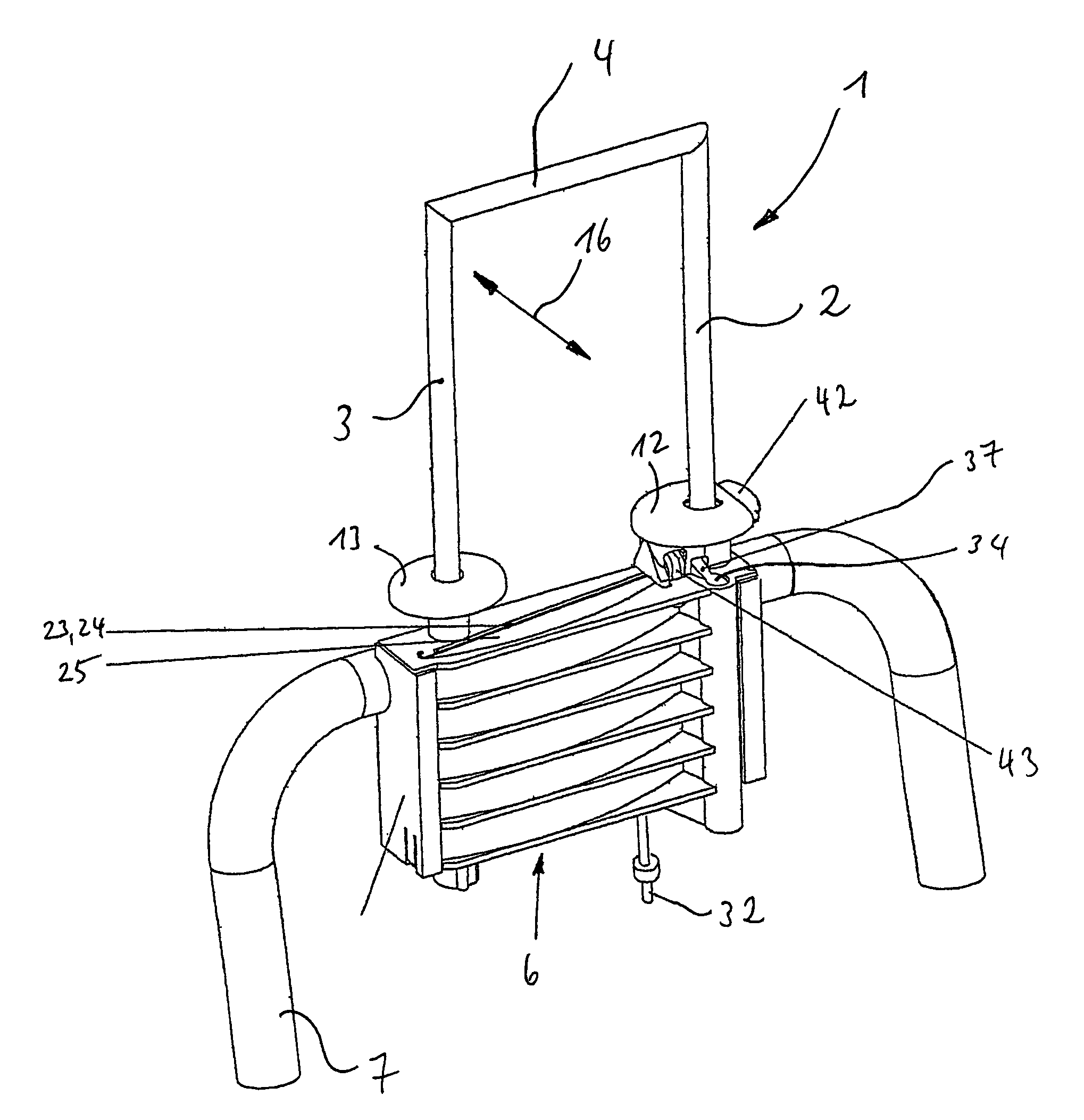
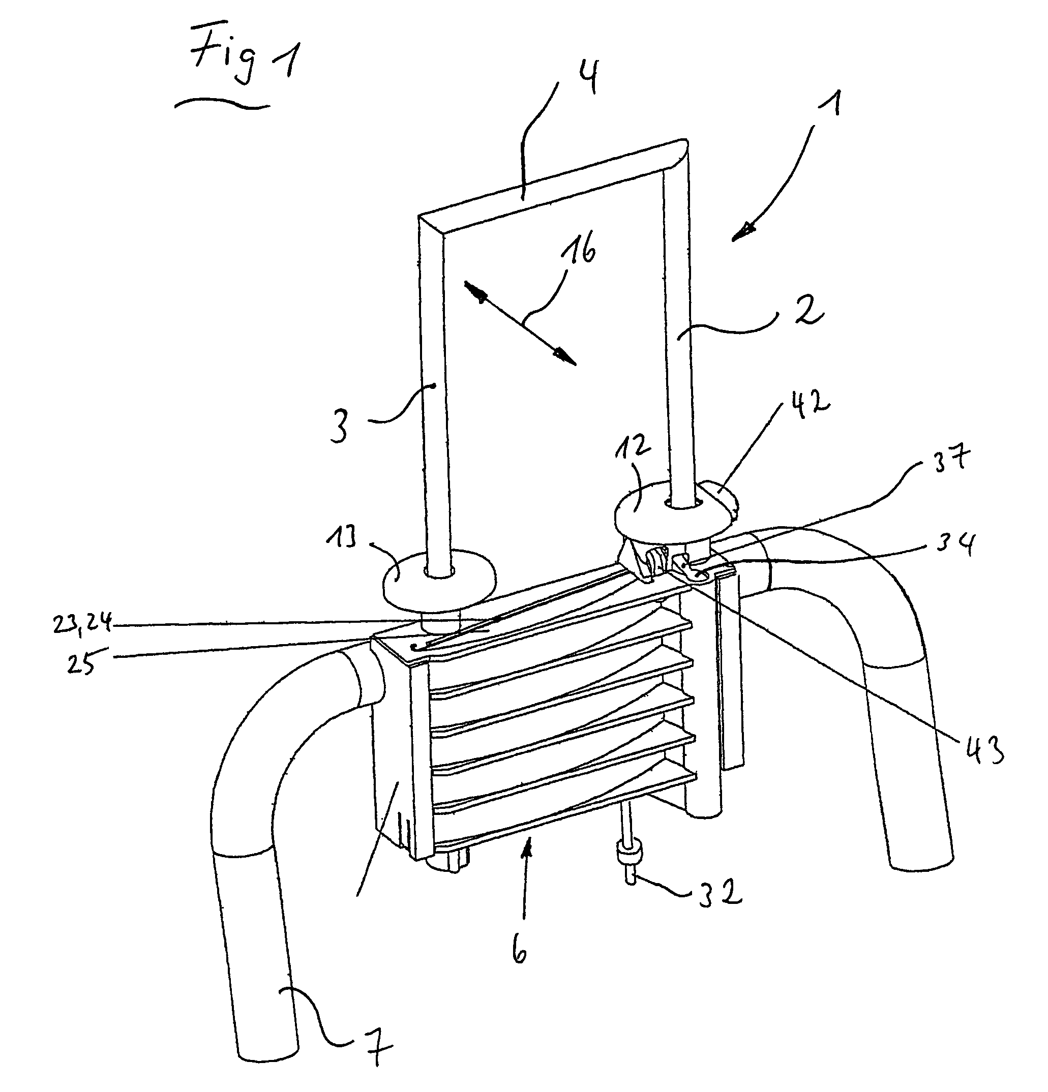
[0045]The headrest of the embodiments shown in FIGS. 1 to 8, possess the following basics of construction, which are also to be found in the embodiments shown in FIGS. 9 to 12, as well as in FIGS. 13 to 25. Each headrest, all designated with the reference number 1, comprises a head-cushion (not shown), which extends from a first holding bar 2 to a second holding ...


PUM


Abstract

A headrest adjustment assembly is disclosed for adjusting the position of a headrest relative to a seatback. The headrest adjustment assembly includes a guide disposed in the seat back, at least one holding bar disposed within the guide, the guide and holding bar being configured with sufficient clearance to allow selective relative longitudinal and transverse sliding, the holding bar being fixed to the headrest, and a clamping element mounted to the seat back for selectively applying a transverse force to the holding bar to thereby fix the position of the holding bar within the guide and prevent relative transverse or longitudinal sliding.

Description

FIELD OF INVENTION[0001]The invention concerns a vehicle seat with a headrest having at least one holding bar, which is height-adjustably secured on at least one support base, which itself is enclosed within a reclinable seat back and affixed to a carrying structure, as well as a headrest adjustment assembly.BACKGROUND OF INVENTION[0002]In order to hold to the lowest possible level the force necessary for the elevation or lowering of a rear seat headrest, whether this be done manually or by remotely actuated, automatic means, it is of advantage if the holding bars of said head rest move within a guide component wherein a radial clearance is present. Counter to this concept, the danger is present, that where such play exists between a holding bar and its support, that the headrest will wobble during driving periods and emit rattling noises. A secure retention of the headrest in the reclining seat back requires, further, auxiliary aids such as springs or motor powered drives, in order...

Claims


Application Information

Patent Timeline
Patent Type & Authority Patents(United States)
IPC IPC(8): B60R22/28B60N2/02B60N2/48
CPCB60N2/0232B60N2/4814B60N2/4829B60N2/482B60N2205/20B60N2002/4897B60N2/821B60N2/829B60N2/815B60N2/897B60N2/02246
Inventor KRAFT, DIETERHOFMOCKEL, JURGEN
Owner ALFMEIER PRAZISION BAUGRUPPEN & SYSTLOSUNGEN
Why Eureka
Try Eureka