Method and apparatus for detecting cracks and delamination in composite materials

a composite material and crack detection technology, applied in the direction of instruments, measurement devices, resonant frequency, etc., can solve the problem that the requirements of fast in-line quality control are not necessarily suitable, and achieve the effect of reducing false positive decisions

Active Publication Date: 2013-08-22
OSTAPENKO SERGEI
View PDF6 Cites 12 Cited by
  • Summary
  • Abstract
  • Description
  • Claims
  • Application Information

AI Technical Summary

Benefits of technology

[0051]To minimize false positive decisions when an acceptable wafer is mistakenly transferred to the separation means, the invention provides for an additional step of inspecting the rejected wafer. It is appreciated that only a small proportion of the wafers will be rejected and, therefore, the step of inspecting the rejected wafer does not need to satisfy stringent requirements of in-line procedures, such as fast handling and short duration of time intervals required for collection and processing of data. The inspection of the rejected wafer preferably comprises an imaging technique, such as, for example, luminescence.

Problems solved by technology

The standard wafer is typically inspected using a range of the characterization methods known in the art, but not necessarily suitable for the requirements of fast in-line quality control.

Method used


Image

  • Method and apparatus for detecting cracks and delamination in composite materials
  • Method and apparatus for detecting cracks and delamination in composite materials
  • Method and apparatus for detecting cracks and delamination in composite materials

Examples


Embodiment Construction

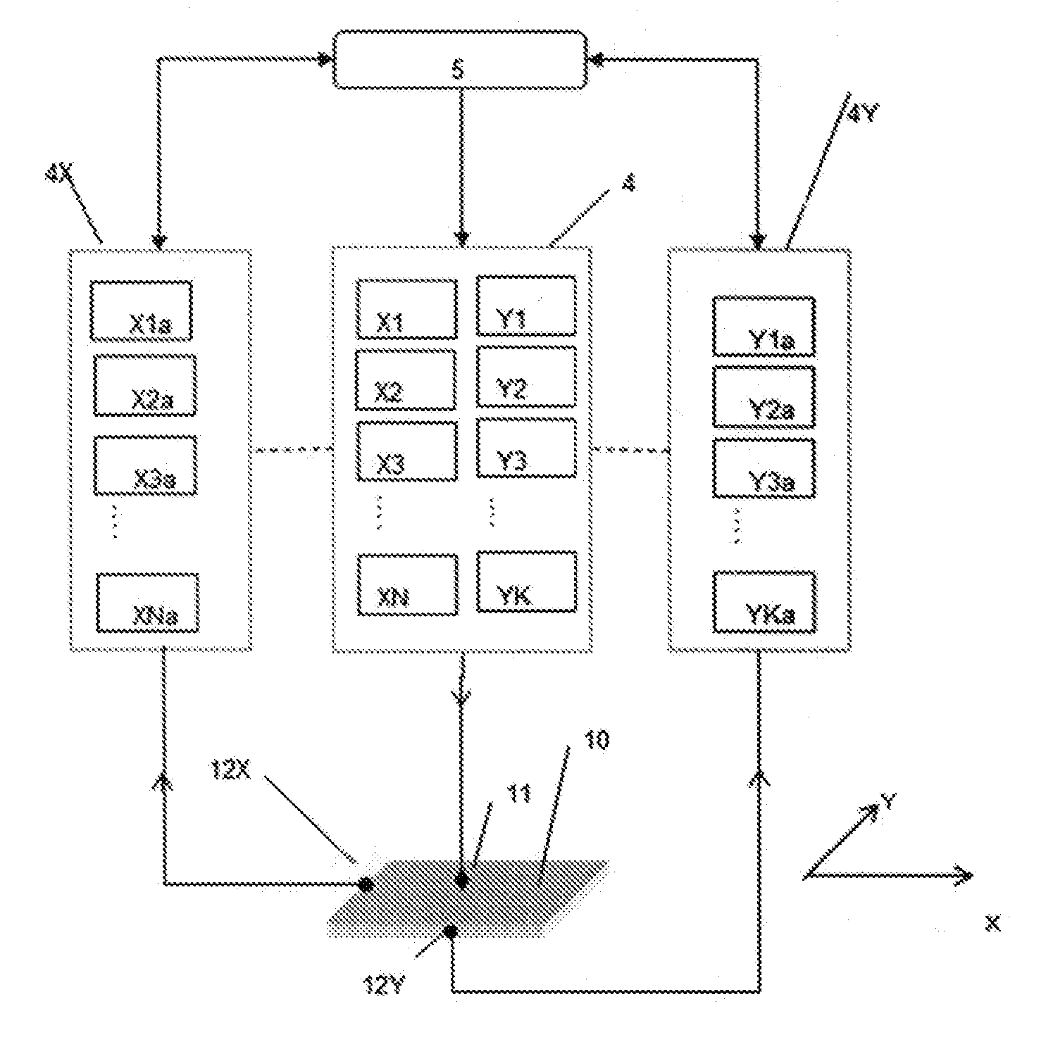
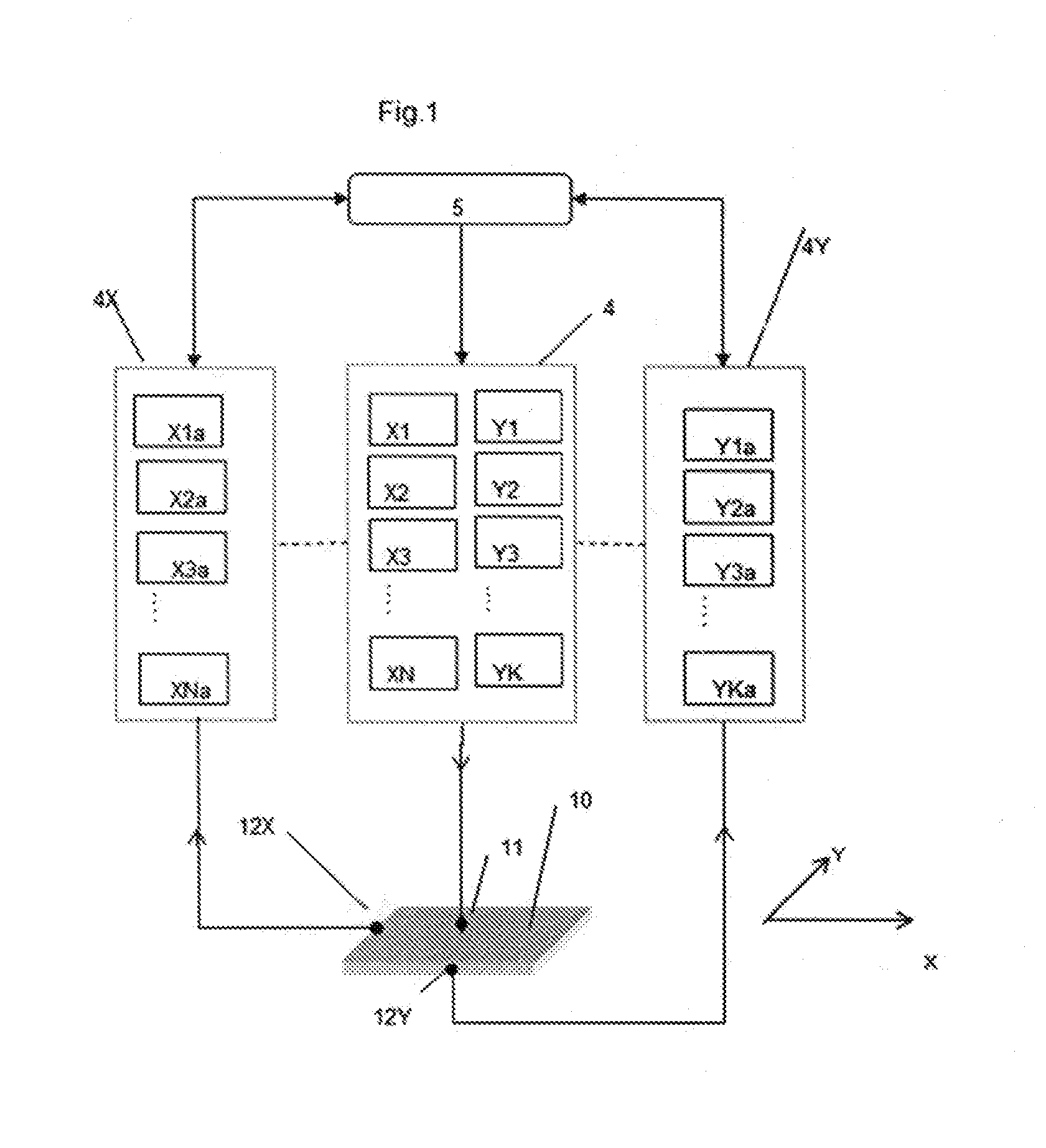
[0108]The chosen first example of the invention, shown in FIG. 1 includes a generator subsystems 4 comprising a number of generators X1, X2, . . . XN, Y1, Y2 . . . YK, each tuned to a certain frequency range and each controlled by a data acquisition and control subsystem. Each of the generators is synchronized with a corresponding amplifier either from a subsystem 4X connected to a sensor 12X, which detects vibrations of a wafer 10 in the X-direction, or from a subsystem 4Y, connected to a sensor 12Y, which detects vibrations of the wafer 10 in the Y-direction.

[0109]It is common for the predetermined frequency range of X-generators to be similar or even identical to that of the analogues Y-generators, such that the generators X1 and Y1 may operate in the same range of frequencies. However, each of the X-generators operates in a different frequency range. The number of generators depends on the number of resonance peaks to be recorded. The number N of X-generators is not necessarily ...


PUM

PropertyMeasurementUnit
thicknessaaaaaaaaaa
sizesaaaaaaaaaa
widthaaaaaaaaaa

Abstract

A method is disclosed for testing for delamination of a first composite component from a second composite component a composite material. The method comprises coupling a broad-band actuator to the composite material and connecting sweeping frequencies to the broad-band actuator for vibrating the composite material. An acoustic sensor is coupled to the composite material for measuring a resonant frequency curve of the vibrating composite material. The measured resonant frequency curve of the vibrating composite material is compared with a reference resonant frequency curve. A delaminated composite material produces a change in the measured resonant frequency curve relative to the reference resonant frequency curve. The method is suitable for detecting delamination in fuel cells as well as ceramic body armor.

Description

BACKGROUND OF THE INVENTION[0001]1. Field of the Invention[0002]The invention relates broadly to methods and apparatus employed in the manufacture of composite materials. More particularly, the invention relates to apparatus and methods for quality control of composite materials such as fuel cell and composite ceramic body armor.[0003]2. Description of the Related Art[0004]Any discussion of the prior art throughout the specification should in no way be considered as an admission that such prior art is widely known or forms part of the common knowledge in the field. State-of-the-art silicon solar cell production is based on highly automated belt-type conveyor configurations. The as-cut p-type Si wafer is typically first subjected to chemical etching which removes saw damaged layers from both front and back surfaces of the wafer or edge damage from the laser cutting of silicon ribbons and then passes through the consecutive process steps including phosphorous diffusion to form a pin j...

Claims


Application Information

Patent Timeline
Patent Type & Authority Applications(United States)
IPC IPC(8): G01N29/12
CPCG01N29/12G01N2291/0258G01N29/4436G01N29/28
Inventor OSTAPENKO, SERGEI
Owner OSTAPENKO SERGEI
Why Eureka
Try Eureka