
Steel structure bridge box turnover device and method

A technology of overturning device and steel structure, which is applied in the direction of bridges, bridge materials, bridge construction, etc., and can solve problems such as personal safety accidents, dumping of large truck cranes, and potential safety hazards

Pending Publication Date: 2021-01-08
HUNAN JINHAI STEEL STRUCTURE
View PDF0 Cites 0 Cited by
  • Summary
  • Abstract
  • Description
  • Claims
  • Application Information

AI Technical Summary

Problems solved by technology

[0003] To carry out the segmental overturning operation of the steel structure bridge box, the industry currently usually uses the aerial lifting and overturning method to perform the overturning operation. Usually, three large cranes (one large truck crane and two factory driving cranes) are needed to cooperate with the aerial lifting and overturning operation. During the hoisting operation, the three cranes must cooperate closely during the section-turning process of the box body. When the box section starts to turn over to the other side, if the driving operation is not properly controlled, and the car hoisting hook is not in time, the bridge box section will collapse. Quickly topple over to the other side and slide in the opposite direction under the action of gravity, which may cause the box body to fall and deform in sections, the driving steel cable to be pulled and broken under the sudden external force, and the driving steel beam to deflect and deform, and the severe one will cause large-scale Car crane toppling over or personal safety accident
Therefore, there is a very serious potential safety hazard in turning over the steel structure bridge box section in the air, which is not conducive to the safe production of steel structure bridges in factories.
The overturning process requires the cooperation of large-scale truck cranes, and the cost of engineering measures is too high, which is not conducive to engineering cost control

Method used


Image

  • Steel structure bridge box turnover device and method
  • Steel structure bridge box turnover device and method

Examples


Embodiment Construction

[0030] Embodiments of the present invention are described in detail below, examples of which are shown in the drawings, wherein the same or similar reference numerals designate the same or similar elements or elements having the same or similar functions throughout. The embodiments described below by referring to the figures are exemplary only for explaining the present invention and should not be construed as limiting the present invention.

[0031] In describing the present invention, it is to be understood that the terms "center", "longitudinal", "transverse", "length", "width", "thickness", "upper", "lower", "front", " Rear", "Left", "Right", "Vertical", "Horizontal", "Top", "Bottom", "Inner", "Outer", "Axial", "Radial", "Circumferential" The orientation or positional relationship indicated by etc. is based on the orientation or positional relationship shown in the drawings, which is only for the convenience of describing the present invention and simplifying the descripti...


PUM


Abstract

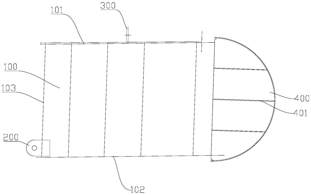
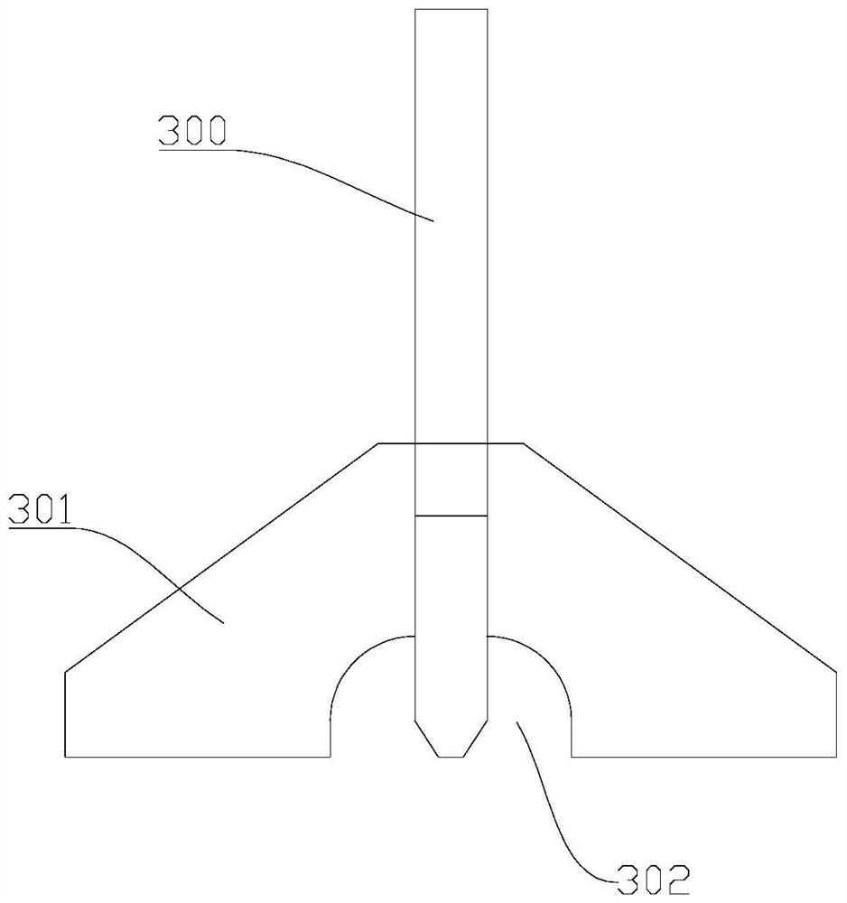
The invention discloses a steel structure bridge box turnover device and method, and the method is achieved based on the steel structure bridge box turnover device. The steel structure bridge box turnover device comprises a first lifting lug, a second lifting lug and a turnover jig frame, wherein the first lifting lug is installed on one end sealing plate, adjacent to a bridge panel, of a box subsection, the second lifting lug is installed on a bridge bottom plate of the box subsection, and the turnover jig frame is installed on another end sealing plate, adjacent to the bridge panel, of the box subsection. The turnover jig frame is provided with a cambered surface. The first lifting lug and the second lifting lug are matched with a crane for operation, so that the box subsection is turnedover around the turnover jig frame, the box subsection can be supported through the turnover jig frame in the process, aerial operation is not needed, the safety is high, and the practicability is high.

Description

technical field [0001] The invention relates to a bridge construction technology, in particular to a steel structure bridge box turning device and method. Background technique [0002] With the application and popularization of steel structure bridges in our country and the increasing requirements of road transportation for bridge pavement width, the application of large steel structure bridges with various ultra-long spans and large width pavement sizes (currently the largest bridge deck width is about 42.5m) is becoming more and more important. more and more. A large steel structure bridge usually consists of a bridge deck, a bridge bottom plate, multiple longitudinal steel webs and various supporting stiffeners to form a longitudinal bridge box. In the process of manufacturing large steel structure bridges in the factory, in order to ensure that the span direction of the bridge meets the design requirements, to ensure that the welds between the bridge deck and the steel ...

Claims


Application Information

Patent Timeline
Patent Type & Authority Applications(China)
IPC IPC(8): E01D21/08E01D2/04E01D101/30
CPCE01D2/04E01D21/08E01D2101/30
Inventor 曾勇熊维刘和平
Owner HUNAN JINHAI STEEL STRUCTURE
Features
  • Generate Ideas
  • Intellectual Property
  • Life Sciences
  • Materials
  • Tech Scout
  • Unparalleled Data Quality
  • Higher Quality Content
  • 60% Fewer Hallucinations
Learn More