Balloon catheter

A balloon catheter, balloon technology, used in balloon catheters, catheters, medical science and other directions

Active Publication Date: 2021-01-08
GOODMAN & COMPANY
View PDF17 Cites 1 Cited by
  • Summary
  • Abstract
  • Description
  • Claims
  • Application Information

AI Technical Summary

Problems solved by technology

[0005] Here, when the lesion in the blood vessel becomes hard due to calcification, it may be difficult to expand the lesion with the balloon.

Method used


Image

  • Balloon catheter
  • Balloon catheter
  • Balloon catheter

Examples


Embodiment Construction

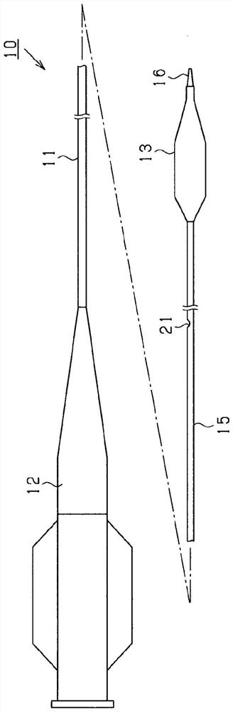
[0032] Hereinafter, one embodiment of the balloon catheter will be described based on the drawings. First, refer to figure 1 A schematic structure of the balloon catheter 10 will now be described. figure 1 It is a schematic overall side view showing the structure of the balloon catheter 10 .

[0033] Such as figure 1 As shown, the balloon catheter 10 includes: a catheter body 11; a hub (Hub) 12 mounted on the base end (proximal end) of the catheter body 11; and a balloon 13 mounted on the front end of the catheter body 11 side (distal side).

[0034] The catheter main body 11 includes an outer tube 15 and an inner tube 16 , and the inner tube 16 passes through the inside of the outer tube 15 . The outer tube 15 is formed of a resin material, for example, a polyamide elastomer. The base end of the outer tube 15 is joined to the hub 12 , and its distal end is joined to the balloon 13 . In addition, the outer tube 15 has a lumen 15a extending over the entire area in the axi...


PUM


Abstract

A balloon catheter 10 that comprises, at a tip-end side, a balloon 13 that can expand and contract. The balloon 13 has: a straight tube section 13c at which the diameter of the balloon 13 becomes greatest during expansion; and a tip-end-side cone section 13d that narrows toward the tip-end side from a tip-end part of the straight tube section 13c. A linear protruding part 30 that extends linearlyalong the axial direction of the balloon 13 is provided to an outer surface of the balloon 13. The linear protruding part 30 includes: a first protruding part 31 that is arranged on the straight tubesection 13c; and a second protruding part 32 that is arranged on the tip-end-side cone section 13d. Over the entire longitudinal-direction length of the second protruding part, the height H2 to whichthe second protruding part 32 protrudes from the outer surface of the balloon 13 is greater than the height H1 to which the first protruding part 31 protrudes.

Description

[0001] Cross-references to related applications [0002] This application is based on Japanese application serial number 2018-130087 for which it applied on July 9, 2018, and uses the description content here. technical field [0003] The present invention relates to balloon catheters. Background technique [0004] Conventionally, balloon catheters have been used for treatments such as PTA (percutaneous angioplasty) and PTCA (percutaneous coronary angioplasty). The balloon catheter has an inflatable and deflated balloon at its distal end. With the balloon catheter, a balloon is introduced in a deflated state into a site in a blood vessel that is narrowed or blocked by a lesion or the like that has occurred, and then the balloon is inflated to expand the site. In addition, the balloon has a straight tube region having the largest diameter when inflated, and a pair of tapered regions provided on the proximal and distal sides of the straight tube region and tapered toward a s...

Claims


Application Information

Patent Timeline
Patent Type & Authority Applications(China)
IPC IPC(8): A61M25/10A61B17/22
CPCA61B17/22A61M2025/109A61M25/104A61M2025/1086A61M2025/1004A61M25/1002A61M2025/1084A61B2017/22051A61B2017/22001A61M2025/1043
Inventor 冈本光正国定嵩
Owner GOODMAN & COMPANY
Why Eureka
Try Eureka