Electric mounting box and cooling storage

A technology for electrical installation and box installation, which is applied in the direction of coolers, electrical components, cooling fluid circulation devices, etc., and can solve problems such as forgetting to connect the connector, complicated operation, and narrow mechanical room

Inactive Publication Date: 2008-08-06
SANYO ELECTRIC CO LTD
View PDF1 Cites 2 Cited by
  • Summary
  • Abstract
  • Description
  • Claims
  • Application Information

AI Technical Summary

Problems solved by technology

[0008] However, in the above-mentioned structure, a metal box for covering the connection part is further provided in the machine room where the space is limited, resulting in a reduction in the size of the machine room.
When connecting the coupler, it is necessary to open and close the metal box, the operation is complicated, and there is a problem of forgetting to connect the coupler

Method used


Image

  • Electric mounting box and cooling storage
  • Electric mounting box and cooling storage
  • Electric mounting box and cooling storage

Examples


Embodiment 1

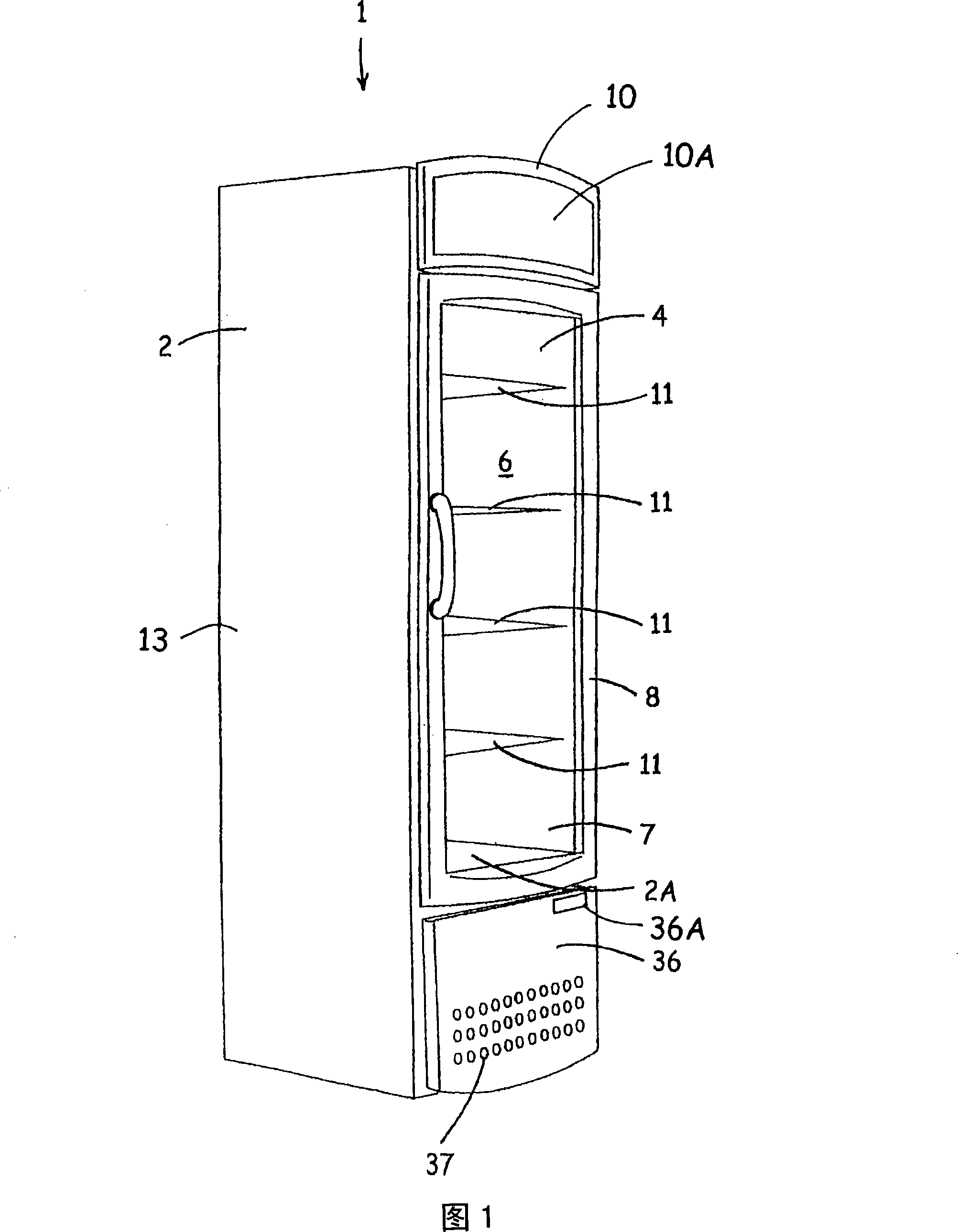
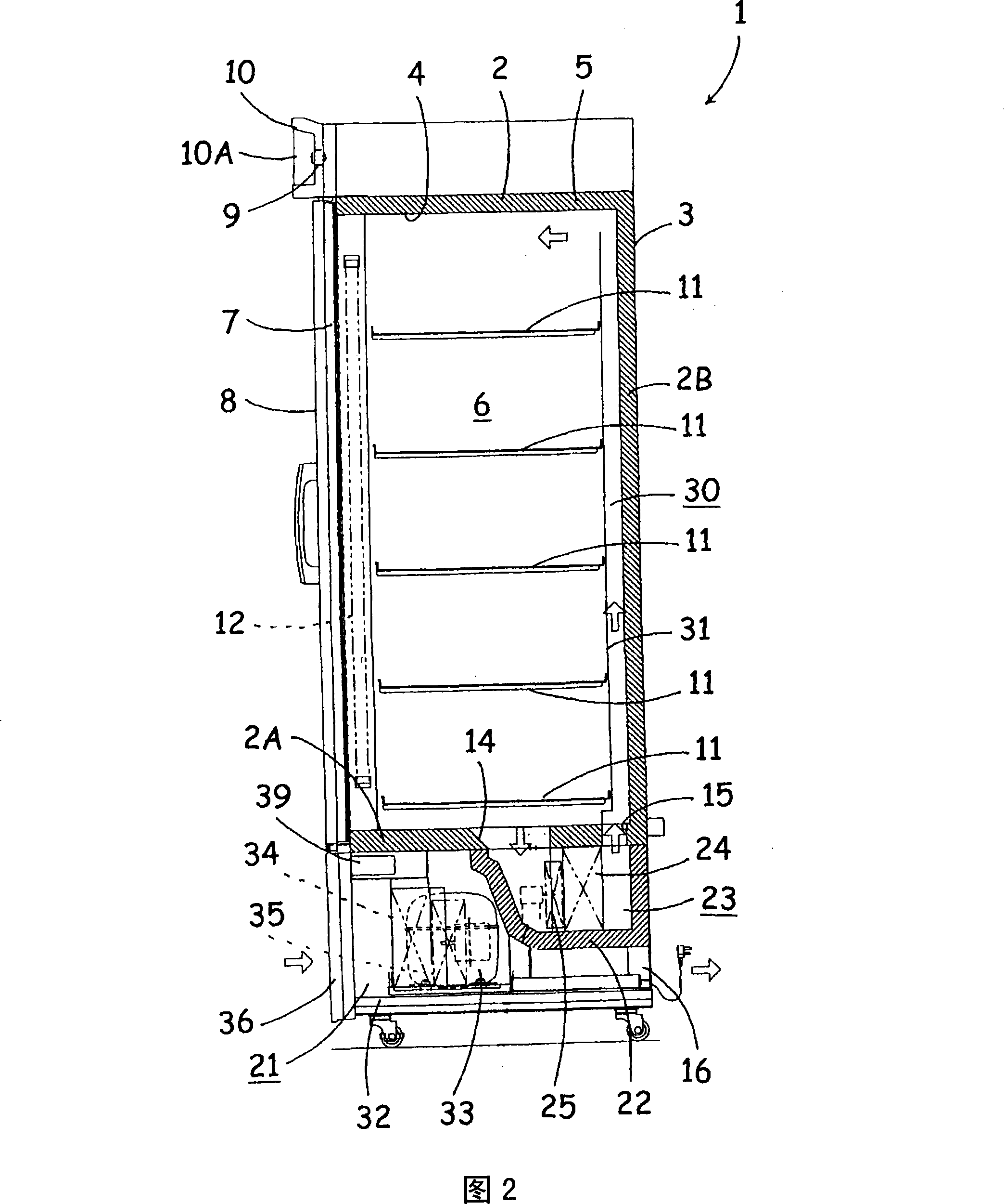
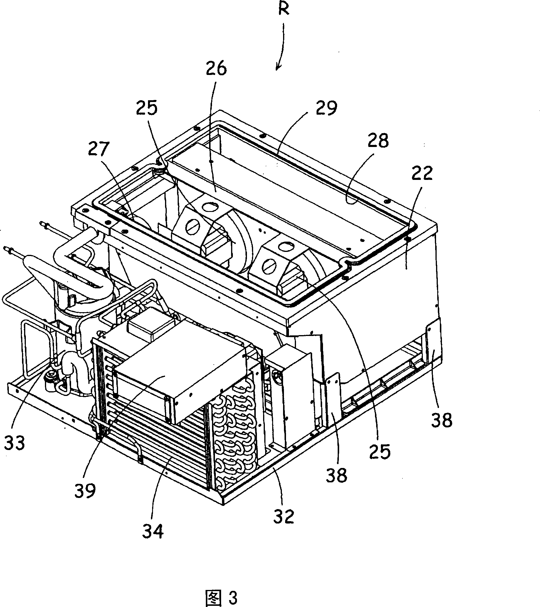
[0045] First, the cooling storage 1 provided with the electrical installation box 39 which is Example 1 is demonstrated, referring FIGS. 1-5. Fig. 1 shows the perspective view of the cooling storage room 1 to which the present invention is applied, Fig. 2 shows the longitudinal section side view of the same cooling storage room 1, Fig. 3 shows the perspective view of the cooling unit, Fig. 4 shows the side view of the cooling unit, and Fig. 5 shows the cooling unit. Perspective view of unit and lifting mechanism L.

[0046] The cooling storage 1 of the present embodiment has a main body constituted by a rectangular heat insulating box 2 opened at the front. The heat insulating box 2 includes: an outer box 3 made of steel plate having an opening at the front; an inner box 4 having an opening at the front; In addition, a store room 6 opening on the front is formed in the heat insulating box 2, and the front opening of the store room 6 is closed openably and closably by a door 8...

Embodiment 2

[0082] First, as a second embodiment, with reference to the partial enlarged cross-sectional views of FIGS. The holding structure in 52 is described. In addition, in each figure, the parts attached with the same symbols as those in Fig. 7 and Fig. 8 have the same mechanism and effect, so the description thereof will be omitted.

[0083] In the above-described embodiment, a flange portion 53 protruding outward toward the cover 42 is formed on the upper end of the coupler mounting member 50 , specifically, on the upper end of the sliding surface 50A. On the other hand, on the side surface of the cover 42 that slides on the sliding surface 50A, except for the above-mentioned engagement hole 42A, in the state where the coupler mounting member 50 is accommodated in the coupler accommodating part 44, the corresponding flange part 53 Engagement holes 54 , 55 are provided through the position corresponding to the flange portion 53 in a state where the coupler mounting member 50 is pu...

Embodiment 3

[0088] Next, as a third embodiment, with reference to the partially enlarged cross-sectional views of FIGS. Be explained. In addition, in each figure, the parts attached with the same symbols as those in Fig. 7 and Fig. 8 have the same mechanism and effect, so the description thereof will be omitted.

[0089] In the above-described embodiment, the protrusion 57 protruding outward toward the cover 42 is formed on the upper end of the coupler mounting member 50 , specifically, on the sliding surface 50A. On the other hand, on the side surface of the cover 42 that slides on the sliding surface 50A, except for the above-mentioned engagement hole 42A, when the coupler mounting member 50 is accommodated in the coupler accommodating portion 44, the position corresponding to the protruding portion 57 , and in the state where the coupler mounting member 50 is pulled out from the coupler accommodating portion 44 to be exposed, engagement holes 58 , 59 are respectively penetrated at pos...


PUM


Abstract

There is disclosed an electric box which can facilitate a connecting operation of electric-box-side coupler and lead-wire-side coupler while suppressing attachment of dust or the like to connecting portions between the couplers. In the electric box (39), electric components (45) are stored in an outer case (40), the electric box is connected to external lead wires (48), the electric box includes the electric-box-side coupler (47) detachably connected to the lead-wire-side coupler (49) attached to distal end of the lead wire (48), and a coupler receiving portion (44) constituted in the outer case (40), the electric-box-side coupler selectively has a received state in which the coupler (47) is positioned in the coupler receiving portion (44) and an exposed state in which the couplers are exposed from the coupler receiving portion (44), and the electric-box-side coupler (47) and the lead-wire-side coupler (49) connected to the electric-box-side coupler (47) are detachably received in the coupler receiving portion (44) in the received state.

Description

technical field [0001] The present invention relates to an electrical component box that accommodates electrical components inside an outer box and connects lead wires from the outside, and a cooling storage that includes the electrical component box. Background technique [0002] Conventionally, a machine room in which a compressor and a condenser are installed is formed in a part of the main body of the cooling storage, and an electrical box for accommodating a power supply board, a control circuit, switches, relays, and the like is further installed in the machine room. [0003] In the cooling storage box disclosed in Patent Document 1, a plurality of lead wires such as a power supply cord and unit wiring are drawn out from the rear of the electrical box. Furthermore, the main body side rail is attached to the top surface of the machine room penetrating back and forth, and the electrical box side rail is similarly attached to the top surface of the electrical box. Theref...

Claims


Application Information

Patent Timeline
Patent Type & Authority Applications(China)
IPC IPC(8): H05K7/00H05K5/00F25D19/00F25D29/00
CPCF25D19/02F25D29/005F25D2400/40F25D2317/0651H01R13/60F25D2317/0661
Inventor 井口治信辻谕白草淳司
Owner SANYO ELECTRIC CO LTD
Why Eureka
Try Eureka