Supercharge Your Innovation With Domain-Expert AI Agents!

Bridge detection equipment mounting mechanism

A technology for equipment installation and bridge inspection. It is used in measuring devices, elasticity testing, and machine/structural component testing.

Active Publication Date: 2021-01-12
邵建波
View PDF11 Cites 0 Cited by
  • Summary
  • Abstract
  • Description
  • Claims
  • Application Information

AI Technical Summary

Problems solved by technology

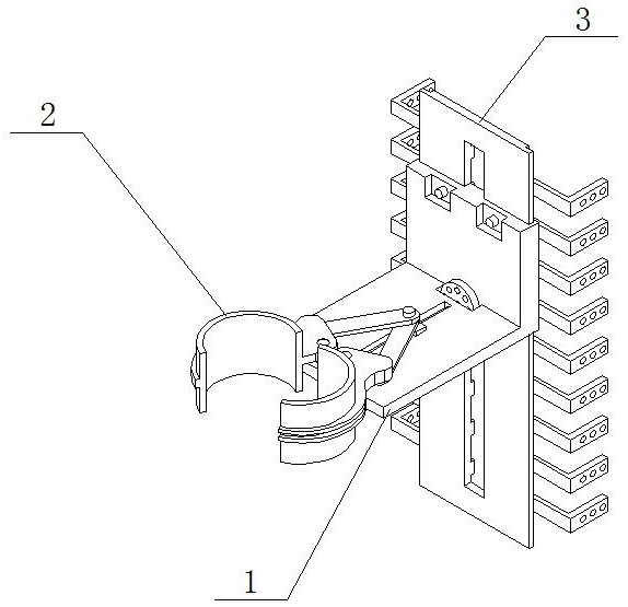
[0004] The purpose of the present invention is to provide a bridge detection equipment installation mechanism, which aims to improve the existing bridge detection equipment which can only be installed on a plane during use, and often needs to be installed on a railing, etc. during the bridge detection process. Installation and use on a cylindrical structure will result in inconvenient installation. At the same time, most of the traditional installation mechanisms adopt a fixed installation method, which is inconvenient to install and disassemble. The problem of multiple disassembly and assembly when using the position

Method used


Image

  • Bridge detection equipment mounting mechanism
  • Bridge detection equipment mounting mechanism
  • Bridge detection equipment mounting mechanism

Examples


Embodiment Construction

[0029]In order to make the purpose, technical solutions and advantages of the embodiments of the present invention clearer, the technical solutions in the embodiments of the present invention will be clearly and completely described below in conjunction with the accompanying drawings in the embodiments of the present invention. Obviously, the described embodiments It is some embodiments of the present invention, but not all of them. Based on the implementation manners in the present invention, all other implementation manners obtained by persons of ordinary skill in the art without creative efforts fall within the protection scope of the present invention. Accordingly, the following detailed description of the embodiments of the invention provided in the accompanying drawings is not intended to limit the scope of the claimed invention, but merely represents selected embodiments of the invention. Based on the implementation manners in the present invention, all other implementa...


PUM


Abstract

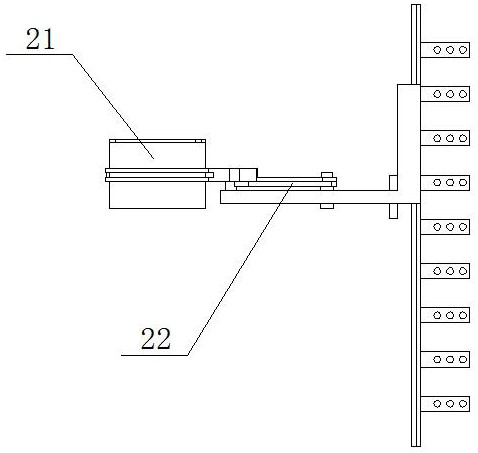
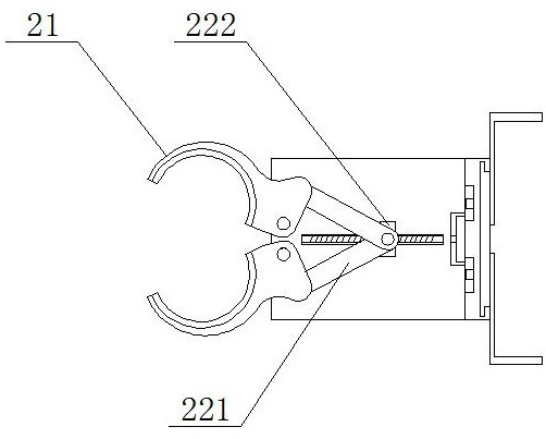
The invention discloses a bridge detection equipment installation mechanism, and the mechanism comprises a connecting plate, a clamping mechanism and an equipment frame; the connecting plate comprisesa bottom plate and side plates, and the side plates are vertically installed on the side face of the bottom plate and fixedly connected with the bottom plate; the clamping mechanism comprises clamping jaws and a driving mechanism, wherein the clamping jaws are symmetrically installed on the head of the bottom plate, and the driving mechanism is fixedly connected with the clamping jaws. The clamping jaws are rotatably connected with the bottom plate, and the equipment frame is mounted in the middle of the side plate, so that a user can stably fix the equipment on the circumference for use through the clamping mechanism when needing to mount the equipment, and the equipment can be mounted and used at any cylindrical position of a bridge; in actual use, the user can stably install the bridgedetection equipment on a right-angle plate firstly, it is guaranteed that the bridge detection equipment can stably detect a bridge in real time, and in the use process, the user can install multiplepieces of detection equipment on the right-angle plate at the same time for use.

Description

technical field [0001] The invention relates to the technical field of equipment installation mechanisms, in particular to a bridge detection equipment installation mechanism. Background technique [0002] A bridge is generally composed of a superstructure, a substructure, a support and ancillary structures. The superstructure is also called a bridge span structure, which is the main structure for crossing obstacles; Or the force transmission device installed at the supporting place of the bridge abutment, and the auxiliary structures refer to the bridge head buttress, conical slope revetment, revetment, diversion works, etc. Most of the bridge inspections are based on the strength of structural concrete, the depth of carbonation of concrete, the location of steel bars and Protective layer thickness, performance and internal defects, steel corrosion potential, chloride ion content, concrete resistivity, steel corrosion polarization current, etc., as well as static strain, st...

Claims


Application Information

Patent Timeline
Patent Type & Authority Applications(China)
IPC IPC(8): G01M5/00
CPCG01M5/0008
Inventor 邵建波袁瀛飞李双杨云鹏李洪亮
Owner 邵建波
Features
  • R&D
  • Intellectual Property
  • Life Sciences
  • Materials
  • Tech Scout
  • Unparalleled Data Quality
  • Higher Quality Content
  • 60% Fewer Hallucinations
Learn More