Bottom filtering fish tank

A fish tank and filter bin technology, applied in the field of lazy fish tanks, can solve the problems of complex use of large oil tanks, single function, affecting landscape effects, etc., and achieve the effect of reducing the blocking viewing surface, easy and convenient use, and improving the survival rate.

Pending Publication Date: 2021-01-22
北京元苡佰科技有限责任公司
View PDF0 Cites 3 Cited by
  • Summary
  • Abstract
  • Description
  • Claims
  • Application Information

AI Technical Summary

Problems solved by technology

[0003] Currently on the market, only small fish tanks have a single function, a single way of filtering water quality, and the effect is relatively weak. Only large fish tanks above 800 mm have a relatively complete filtration system, but large fish tanks have complex structures and occupy a large space. It is heavy and difficult to move, the cost is high and the use of materials is limited. Later, it will be sent to users in the form of scattered parts, which requires professional on-site assembly. For most fish farming beginners, the use of large oil tanks is complicated and inconvenient , higher maintenance cost
[0004] In addition, the existing desktop small fish tanks basically adopt the back filtration scheme, the top cover filtration scheme, the built-in filtration scheme, the plug-in filtration scheme or the external filtration scheme. All of the above schemes have a characteristic. External, or external pump, or block the viewing area of ​​the fish tank, for small fish tanks, it will seriously affect the landscape effect

Method used


Image

  • Bottom filtering fish tank
  • Bottom filtering fish tank
  • Bottom filtering fish tank

Examples


Embodiment Construction

[0036] The following will clearly and completely describe the technical solutions in the embodiments of the present invention with reference to the accompanying drawings in the embodiments of the present invention. Obviously, the described embodiments are only some, not all, embodiments of the present invention. Based on the embodiments of the present invention, all other embodiments obtained by persons of ordinary skill in the art without making creative efforts belong to the protection scope of the present invention.

[0037] The core of the invention is to provide a bottom filter fish tank with convenient use, good filtering effect and great landscape effect.

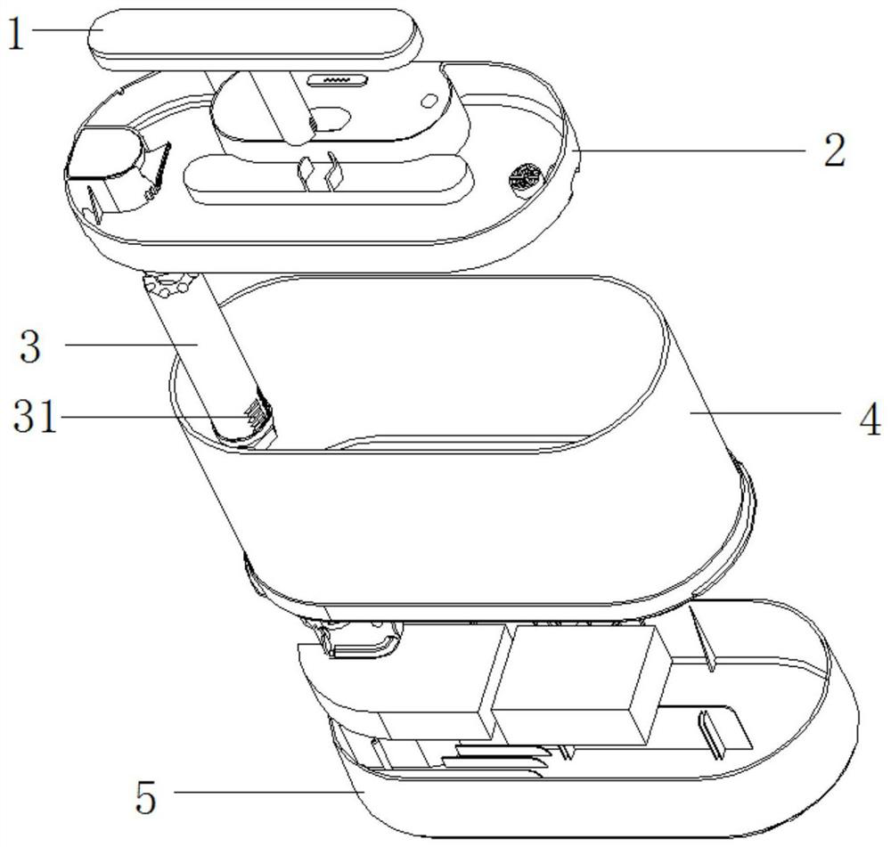
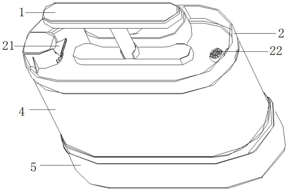
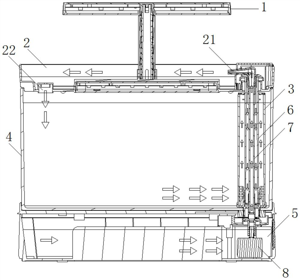
[0038] Please refer to Figure 1 to Figure 6 , figure 1 It is the explosion schematic diagram of the specific embodiment of bottom filter fish tank provided by the present invention; figure 2 It is the three-dimensional schematic diagram of the specific embodiment of bottom filter fish tank provided by the present...


PUM


Abstract

The invention discloses a bottom filtering fish tank which comprises a transparent tank body, a bottom filtering bin arranged at the bottom of the transparent tank body and used for filtering water flow and culturing bacteria, and an upper cover bin arranged at the upper portion of the transparent tank body and used for culturing aquatic plants, sand and stones. The lower end of a first pipe bodyis connected to a water outlet of the bottom filtering bin; the upper end of the first pipe body is connected to a water inlet connected to the upper cover bin; the lower end of a second pipe body isconnected to a water inlet of the bottom filtering bin, and a second water inlet for water to enter the second pipe body is formed in the side wall of the upper end of the second pipe body; a first water inlet hole for water in the transparent tank body to flow into the third pipe body is formed in the side wall of the lower end of the third pipe body; and a water pump is arranged in the bottom filtering bin, a water outlet of the water pump is connected to the first pipe body so as to pump filtered water flow into the upper cover bin, and the upper cover bin is provided with a water inlet connected to the transparent tank body, so that the water pumped into the upper cover bin can flow into the transparent tank body. The bottom filtering fish tank has the advantages of convenience in use,convenience in tabletop cultivation, good filtering effect, good landscape effect and the like.

Description

technical field [0001] The invention relates to the technical field of lazy fish tanks, and more specifically relates to a bottom filter fish tank. Background technique [0002] Fish tanks are a common item for people to raise fish for leisure. During the process of raising fish, it is necessary to continuously filter the water in the fish tank to improve the water quality. [0003] Currently on the market, only small fish tanks have a single function, a single way of filtering water quality, and the effect is relatively weak. Only large fish tanks above 800 mm have a relatively complete filtration system, but large fish tanks have complex structures and occupy a large space. It is heavy and difficult to move, the cost is high and the use of materials is limited. Later, it will be sent to users in the form of scattered parts, which requires professional on-site assembly. For most fish farming beginners, the use of large oil tanks is complicated and inconvenient , and the ma...

Claims


Application Information

Patent Timeline
Patent Type & Authority Applications(China)
IPC IPC(8): A01K63/00A01K63/04A01K63/06A01G31/02A01G7/04
CPCA01G7/045A01G31/02A01K63/003A01K63/04A01K63/042A01K63/045A01K63/047A01K63/06Y02P60/21
Inventor 王剑锋
Owner 北京元苡佰科技有限责任公司
Why Eureka
Try Eureka